- Science Toys
- Magnetism
- Electromagnetism
- Electrochemistry
- Radio
- Thermodynamics
- Aerodynamics
- Light and optics
- Simple laser communicator
- Make your own 3D pictures
- Making permanent rainbows.
- A solar powered marshmallow roaster
- Make a spectroscope from a CD.
- The impossible kaleidoscope
- Make a solar hotdog cooker
- Exploring invisible light
- A high resolution spectrograph.
- Time-lapse photography.
- High speed photography.
- Stacking photos for high depth of field.
- Biology
- Mathematics
- Computers and Electronics
Building a Three-Penny Radio.
A crystal radio is nice because it needs no power, and the materials can all be home-made or at least found around the house. But the crystal radio needs a big antenna, and a good ground, and so is not very portable. To get away with using a much smaller, portable antenna, we will need to amplify the tiny signal it receives. This requires a portable power supply, such as a battery. Our next toy is a portable radio. It can be powered from a tiny 1.5 volt battery, or from a battery made from copper wire and aluminum foil sitting in a glass of lemonade, a soft drink, or a beer, or by a few small commercial solar cells. The heart of the radio is a special 10 transistor integrated circuit in a tiny three-legged bit of plastic. This circuit comes ready-made with several amplifiers, the detector, and an Automatic Gain Control circuit that boosts the level of faint stations to match the strong ones, so no volume control is needed. The final radio has excellent performance, pulling in weak stations, and preventing nearby strong stations from overwhelming the weak ones next to them on the dial. We call the radio a "Three Penny" radio because we use three shiny pennies as anchors for the various parts the radio needs. This makes the construction very easy. If you have never soldered anything before, this is a great project to start with. It is very forgiving of the type of soldering usually done by beginners, and all the parts are widely separated, making the job much easier than with other circuits. Soldering irons and solder are inexpensive tools you can find at a local electronics store such as Radio Shack. The three-penny radio needs these parts: (We carry a bundle of all the necessary parts in our catalog.)- Three shiny pennies
You can clean them up with polish, or you can use brand new ones. - A tuning coil
You can wind one by hand, but in this project we use a much smaller coil with a ferrite rod inside, from our catalog. The coil in the photos has only two wires. The one we ship in the catalog is the improved coil with four wires that we used in the 10 minute radio. - An MK484-1 AM Radio Integrated Circuit
This is the heart of the radio. We carry it in our catalog. - A Piezoelectric earphone
Also in our catalog. - A tuning capacitor
We use a variable capacitor, from 0 to 160 picofarads. We have it in our catalog. - A 100,000 ohm resistor
This resistor will have four colored bands on it. The colors will be brown, black, yellow, and gold. - A 1,000 ohm resistor
This resistor will also have four colored bands on it. The colors will be brown, black, red, and gold. - A 0.01 microfarad capacitor
This capacitor will be marked something like ".01M" or "103". - Two 0.1 microfarad capacitors
These capacitors will be marked something like ".1M" or "104". - A 1.5 volt battery
- (optional) A 1.5 volt battery holder
Click on photo for a larger picture
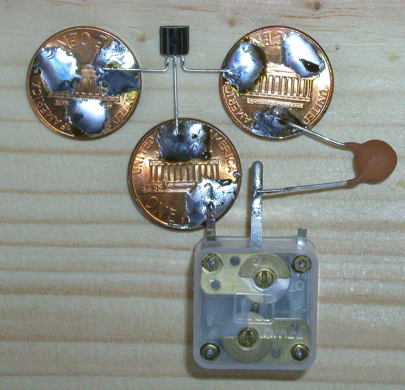
We start by placing the three shiny pennies on an old board where we will work. An old board will not be missed if a hot soldering iron burns a black spot in it. Don't work on a nice tabletop. The pennies should be clean and bright. This will help the solder stick to them and flow onto their surface. Solder will not stick to a dirty penny. I used clean relatively new pennies that I didn't have to clean or polish. Old pennies can be cleaned with brass polish or by simply leaving them in a mixture of vinegar and salt for a half-hour or so. We are going to build the radio "upside-down", so that all of our soldering will be neatly hidden from view when we turn the radio over when we are finished. Select which side of the penny you want to be visible, and place that side face down. I chose "heads" to be visible, so the "tails" side is facing up in the next photo. The first thing we will do is bend the wires of the integrated circuit so the outside wires stick out like the arms of a scarecrow. This makes the soldering much easier, since the wires are not close together. The integrated circuit has a flat side and a rounded side. The flat side will face up when we are done, so we make it face down while we build our radio upside-down. The orientation of this part is important. The three legs are the "output", the "input" and the "ground" when it is upside-down like this. (When face up, the "ground" will be on the left, and the "output" will be on the right.) If the integrated circuit is not flat-side-down at this point, then we won't be connecting to the right parts when we are done, and the radio won't work.
Click on photo for a larger picture
It usually takes a while to heat up a penny enough to melt solder onto it. Hold the soldering iron firmly on the spot on the penny where we want the solder to be, and feed the wire solder onto the hot penny as it melts. It doesn't take much solder. It is often a good idea to make a small blob of solder on the penny first, and then place the wire of the integrated circuit onto the blob of solder, and reheat both until the solder wets the wire. You will see that we have done just that in the photo. The two top pennies have three blobs of solder on them, and the bottom penny has two blobs of solder. Solder all three of the wires to the three pennies.
Click on photo for a larger picture
The next step is to solder the variable capacitor to the bottom penny. Remember to place the variable capacitor upside down. The variable capacitor has three legs, but we will only be using two of them. This variable capacitor is actually two capacitors in one, and they share the middle leg. We will only be using one of the capacitors. The two capacitors have different values, and we are using the 160 picofarad side (the left in the photo) and leaving the 60 picofarad side unconnected. As the photo shows, I have cut off the third leg to remind me which side to use.
Click on photo for a larger picture
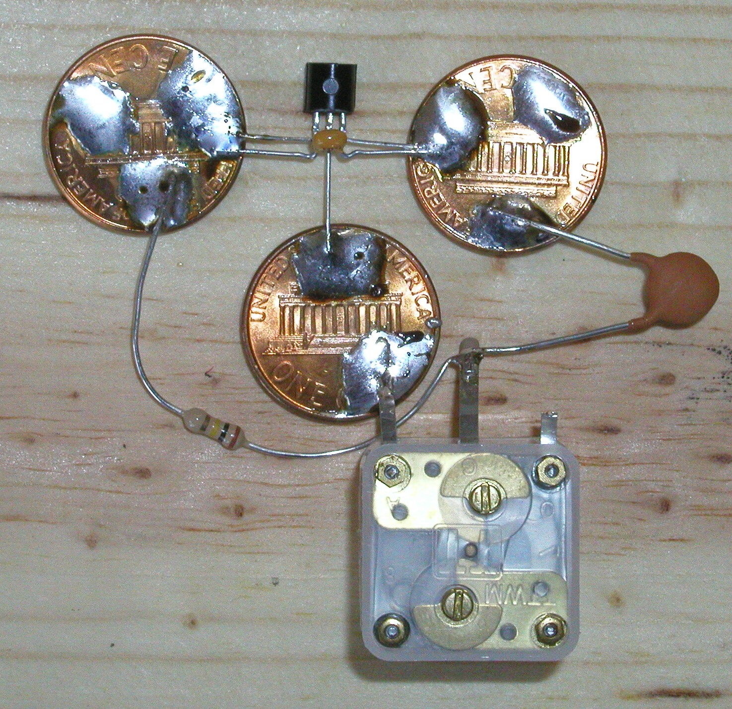
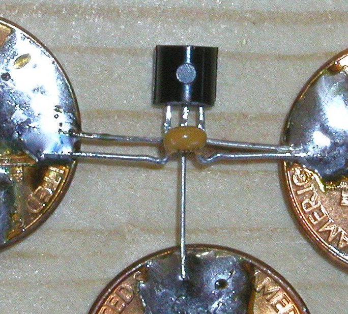
The next part we add to the circuit is the small fixed value capacitor, the one marked ".01M" or "103". Both of these markings mean the same thing -- the capacitor has the value 0.01 microfarads (we can also say 10 nanofarads, but the tendency in the industry is to use microfarads). The small capacitor is soldered to the middle leg of the variable capacitor, and to the penny. It is probably easiest to solder it to the penny first, and then to bend it so the other leg touches the middle leg of the variable capacitor, and then solder them where they touch. Always make sure metal parts to be soldered are touching before you solder them -- this makes a stronger joint.
Click on photo for a larger picture
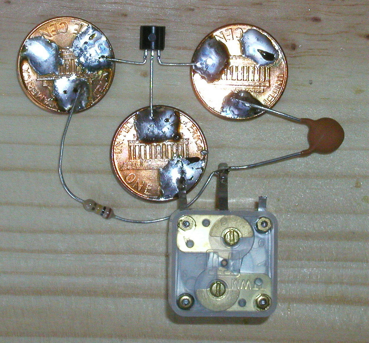
The next part is the 100,000 ohm resistor. In the photo, you can see the color coded bands on it. They are brown, black, yellow, and gold. This resistor must be soldered to the middle leg of the variable capacitor at one end, and to the top left penny at the other end. It must not touch any other metal part along the way.

Click on photo for a larger picture
In the photo above, we have turned the project over for a moment to show that the resistor is not touching anything except where it is soldered. Now we solder the 0.1 microfarad capacitor to the two top pennies. This capacitor will be marked "104", or sometimes "0.1M". If the leads are short, the capacitor can be stretched across the integrated circuit as shown in the photos above and below.
Click on photo for a larger picture
If the leads are long, the capacitor can be placed above the integrated circuit. Make sure the wires from the capacitor do not touch the middle wire of the integrated circuit.
Click on photo for a larger picture
Next we will connect the wires from the piezoelectric earphone to the 1,000 ohm resistor, and to the other 0.1 microfarad capacitor. The color codes on the 1,000 ohm resistor are brown, black, red, and gold.
Click on photo for a larger picture
Now we solder the resistor to the top left penny.

Click on photo for a larger picture
In the photo below, we have wrapped the red (positive) wire from the battery holder around the resistor wire. The black wire goes to the top right penny. Now we solder all of the connections.

Click on photo for a larger picture
If you are going to use lemonade for the battery, just solder a longish wire to each of these spots instead of the battery holder. I like to use red wire for the positive side, and black wire for the negative side, just like they do for the battery holder. This helps me remember which wire goes where later.
Click on photo for a larger picture
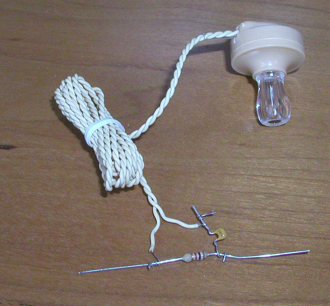
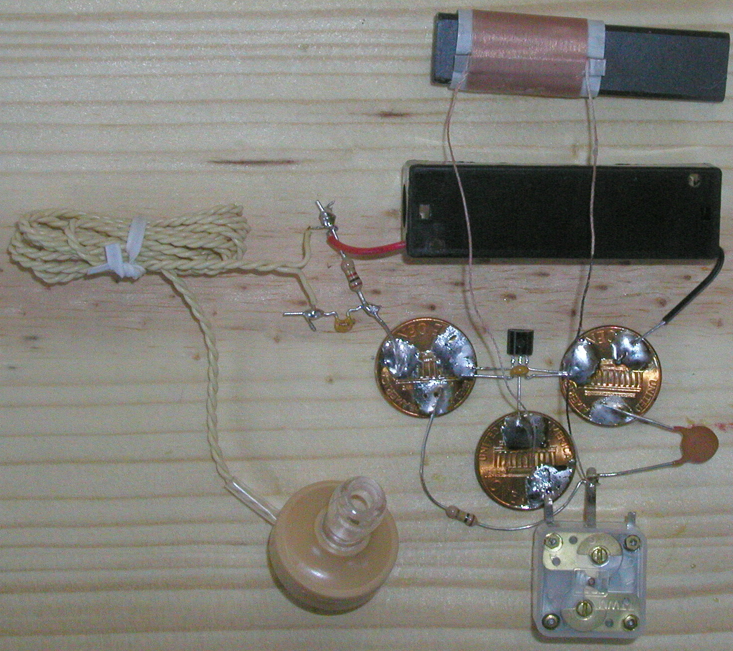
The next step is to solder the wires from the coil to the legs of the variable capacitor. In the photo above, I have placed a piece of white paper over the project, to make it easier to see the fine wires in the photo. You won't need the paper when you build the radio, it is just to make the parts in the photo easier to see. If you are using the 4 wire coil from our catalog or the kit, connect the unpainted wire to the left terminal of the capacitor, and the black wire to the center terminal of the capacitor. The red wire is for an optional external antenna, and the green wire is for an optional ground connection. The radio works fin with these wires unconnected, but will pick up distant stations more easily if they are connected as we did in the 10 minute radio project. The ferrite rod in the coil is not glued in place, and can slide easily into and out of the coil. This is important, because we will be sliding the ferrite rod in and out of the coil later, to adjust the tuning.
Click on photo for a larger picture
The photo above shows the project so far, without the paper in the way. At this point the radio is actually complete. You can probably hear sounds from the earphone if you put the battery into the holder. We will discuss how to tune the radio in a moment.
Click on photo for a larger picture
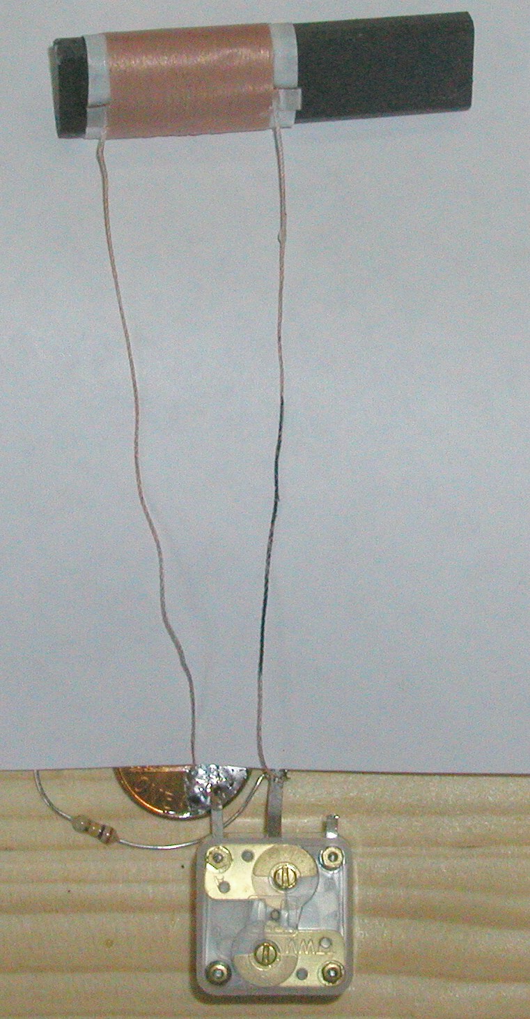
Now we finally get to turn the radio over, so it is right-side-up. The photo shows three push-pins placed around the variable capacitor. We will discuss why in a little bit. The capacitor is now glued down to the board. You might notice that we are now using a nice clean board, since we are done soldering. The radio can be used as it is (we will add a finishing touch in a moment). It is tuned in two ways. First, you can slide the ferrite rod very slowly into and out of the coil. This is a coarse adjustment, and getting exactly the station you want can be difficult this way, since a tiny movement of the rod can change the tuning to a different station. Finer tuning is done by turning the brass rod in the variable capacitor. To make this easier to do, and to make it easier to make fine adjustments, we will make a large knob out of a plastic lid from a jar or can that we no longer need for anything else.
Click on photo for a larger picture
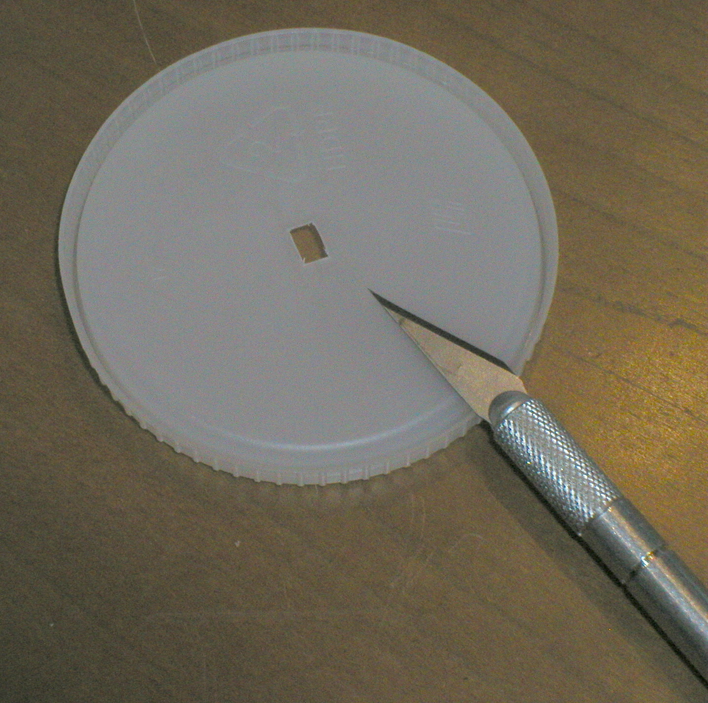
With a small, sharp knife, cut a small rectangle out of the center of the lid. The rectangle should be just a bit smaller than the brass rectangular top of the rod in the variable capacitor, so it will make a very tight fit when we press it onto the brass rod.
Click on photo for a larger picture
The photo above shows the tuning knob in place. The three push-pins hold up the knob so it doesn't wobble. With the large knob, it is easy to select just the station you want to hear. Since the ferrite rod is still loose in the coil, the radio is not yet very portable. At this point you need to find out where to place the rod so that all of the stations in the AM band can be tuned using just the variable capacitor. This is done by turning the capacitor all the way to the left, and then sliding the ferrite rod into the coil until you hear the first station. Now you can tape the rod onto the board, or glue it there with some silicone rubber glue. You can also glue down the battery holder if you like. Your Three-Penny Radio is now complete!
How does it do that?
At this point in the book, if you have been reading from the beginning of the chapter, you probably already know most of the science behind how this radio receiver works, since it is very similar to a crystal radio. Like a crystal radio, this is a "Tuned Radio Frequency" receiver. That means it listens to the radio signal directly. It does not contain an oscillator like some other radio circuit designs (such as superheterodyne and regenerative radios). The coil and variable capacitor join together to form a "tank circuit" that selects which radio station you want to listen to. Tank circuits, and capacitors are covered in considerable detail and length in the page called Adding a capacitor (or three) in the section titled "Building a crystal radio out of household items". The main difference between this radio and a crystal radio is that the integrated circuit in this radio not only has the crystal inside it, but it has amplifiers and an Automatic Gain Control. The antenna coil (the little coil with the ferrite rod inside) generates tiny amounts of electricity as the radio waves wash over it. An amplifier is a circuit that uses that tiny amount of electricity to control a much larger flow of electricity from the battery. It is like using the water from a garden hose to move the nozzle of a firehose, putting a huge amount of water anywhere you wanted it, using only a little water from the garden hose. The Automatic Gain Control circuit controls how much amplification is used. It turns up the volume on weak stations, so they sound as loud as strong stations do. This is why we don't need a volume control on our radio -- all the stations are close to the same loudness (no AGC circuit is perfect -- you can still tell which stations are powerful nearby stations and which ones are far away or weak). The piezoelectric earphone is also covered in the first page of the section "Building a crystal radio out of household items". In the radio shown in the photos, we use a 1.5 volt battery (in this case a small "N" cell, but you could use a "D", "C", "AA", or "AAA" cell just as easily). The radio will work with battery voltages as low as 1.1 volts, or as high as 1.8 volts. The current needed is very small -- only 3 milliamps. This tiny amount of electricity is easily obtained from homemade batteries, or small commercial solar cells.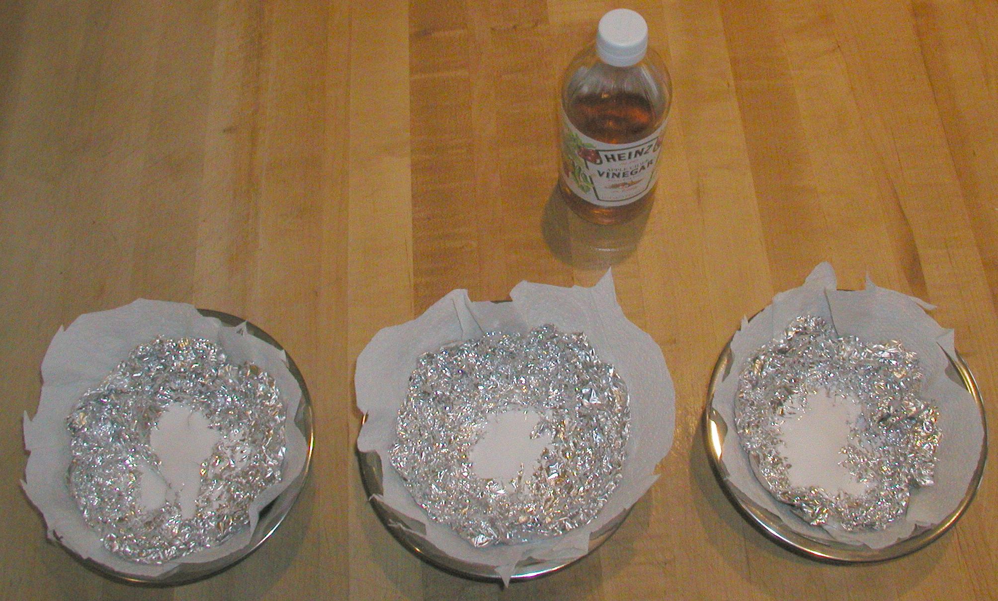
Click on photo for a larger picture
One simple homemade battery is just a piece of crumpled aluminum foil in a stainless steel bowl of vinegar and salt. The foil is kept from touching the bowl by a piece of paper tower or newspaper.
Click on photo for a larger picture
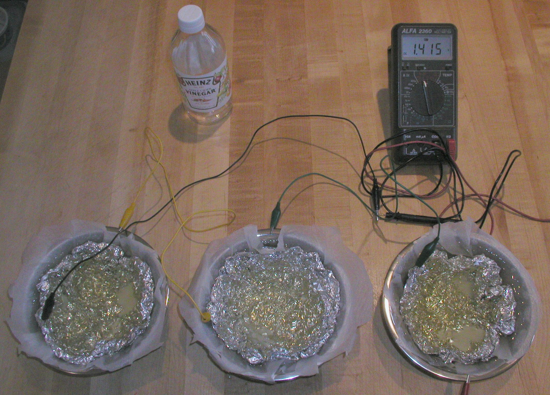
The stainless steel bowl and aluminum foil must not touch one another. You can get higher voltage by connecting the bowl of one battery to the aluminum foil of the other battery (this is a series connection). The radio needs between 1.1 volts and 1.8 volts to operate. But it also needs at least 0.1 mulliamps of current. The specifications say it needs 3 milliamps, but as you can see in the photo, we are using only 0.15 milliamps, and the radio has very nice volume. The voltage is determined by how many bowls you have. The current is determined by how much surface area the bowls and aluminum foil have. Using bigger bowls and more foil will produce more current.
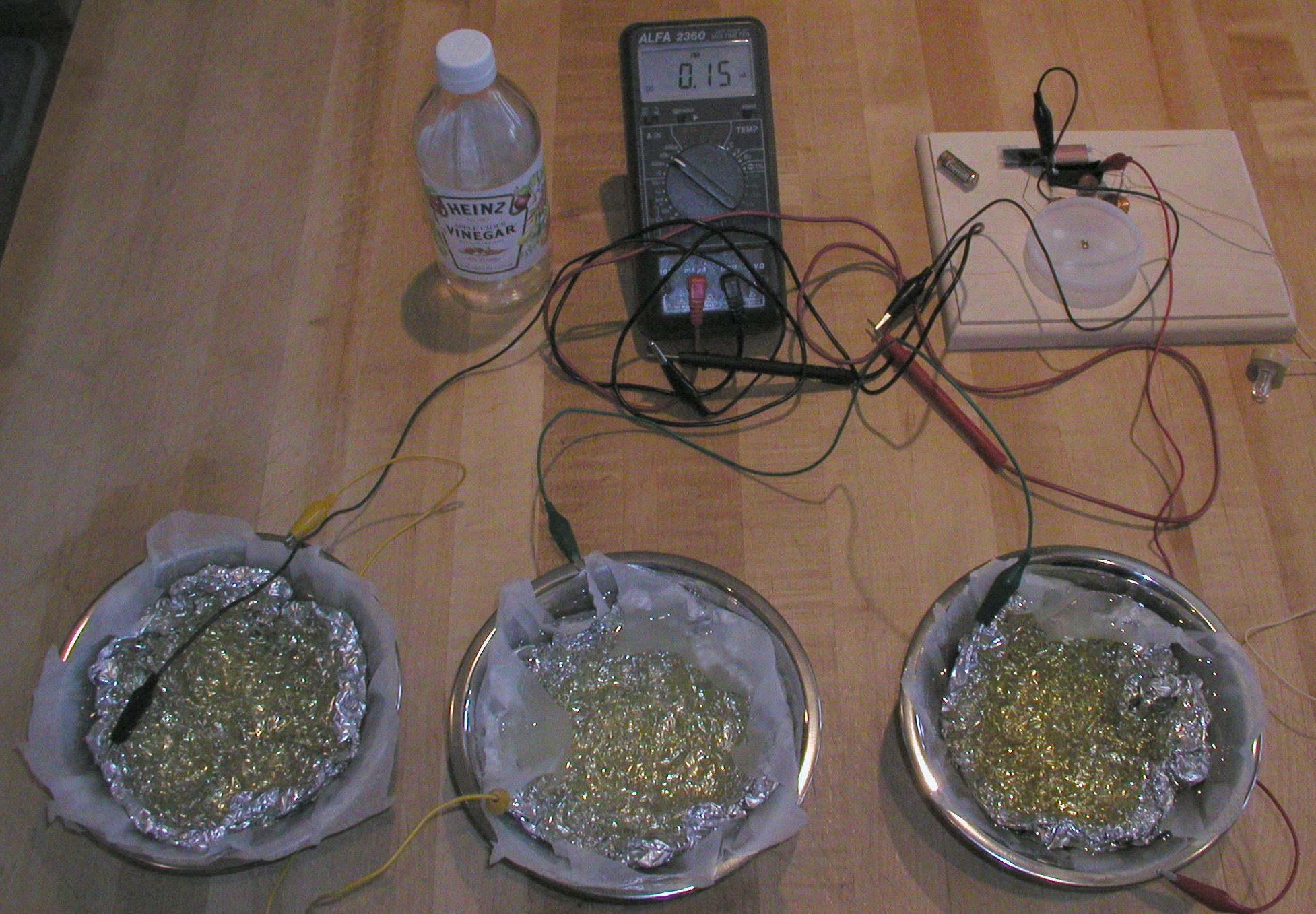
Click on photo for a larger picture
The bowl is the positive wire, and connects to the radio where the red wire from the battery holder went. The aluminum foil is the negative side of the battery, and connects where the black wire from the battery holder connected. You can see the alligator clips attached to the battery holder if you look at the larger photo (click on the small photo). You can try soft drinks, or lemonade instead of the vinegar. The salt usually helps a lot though. Some people power their radios with beer. Depending on the beer, you may need more than three bowls. Adding salt to the beer will keep it from disappearing into curious bystanders.
Some fun packaging
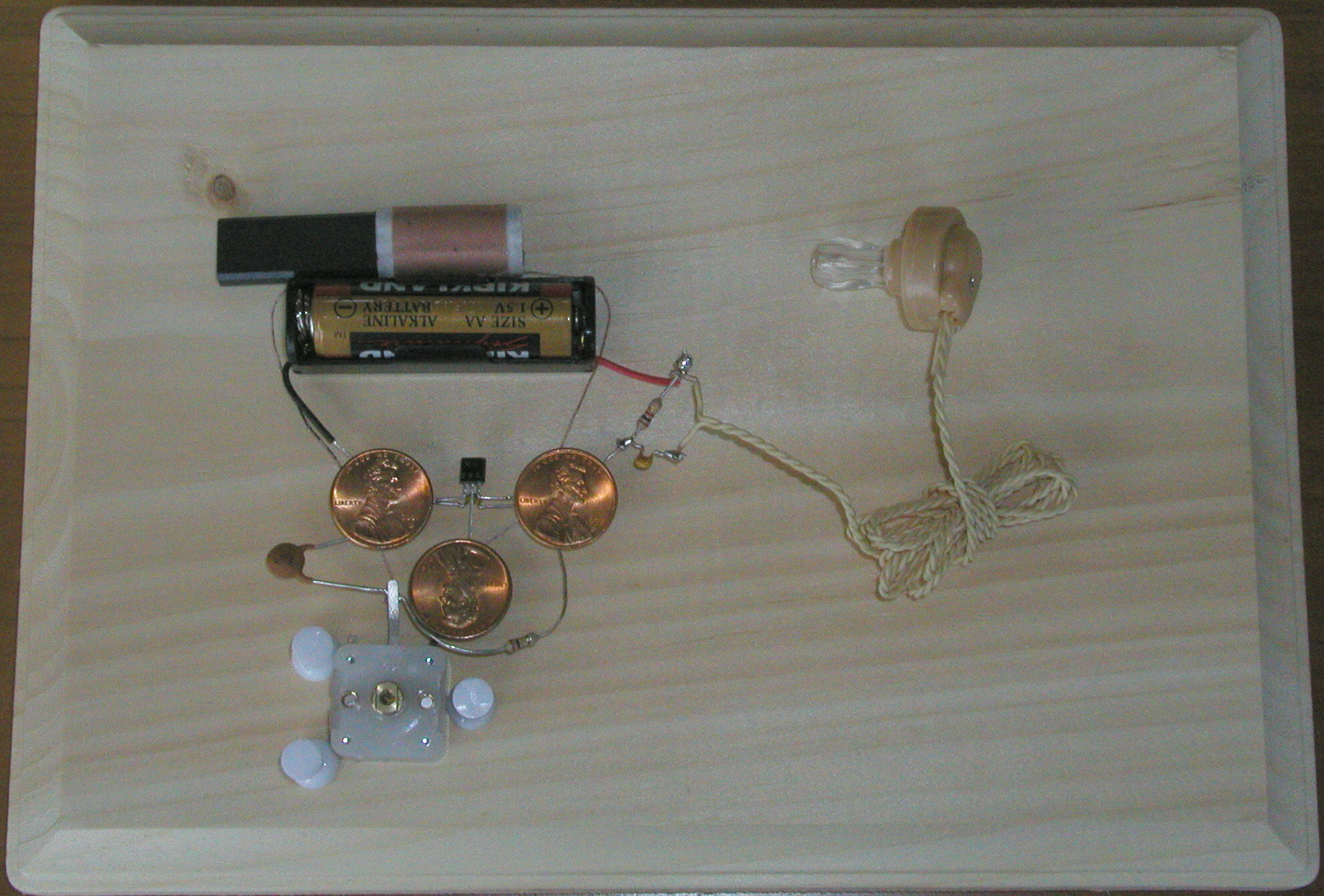
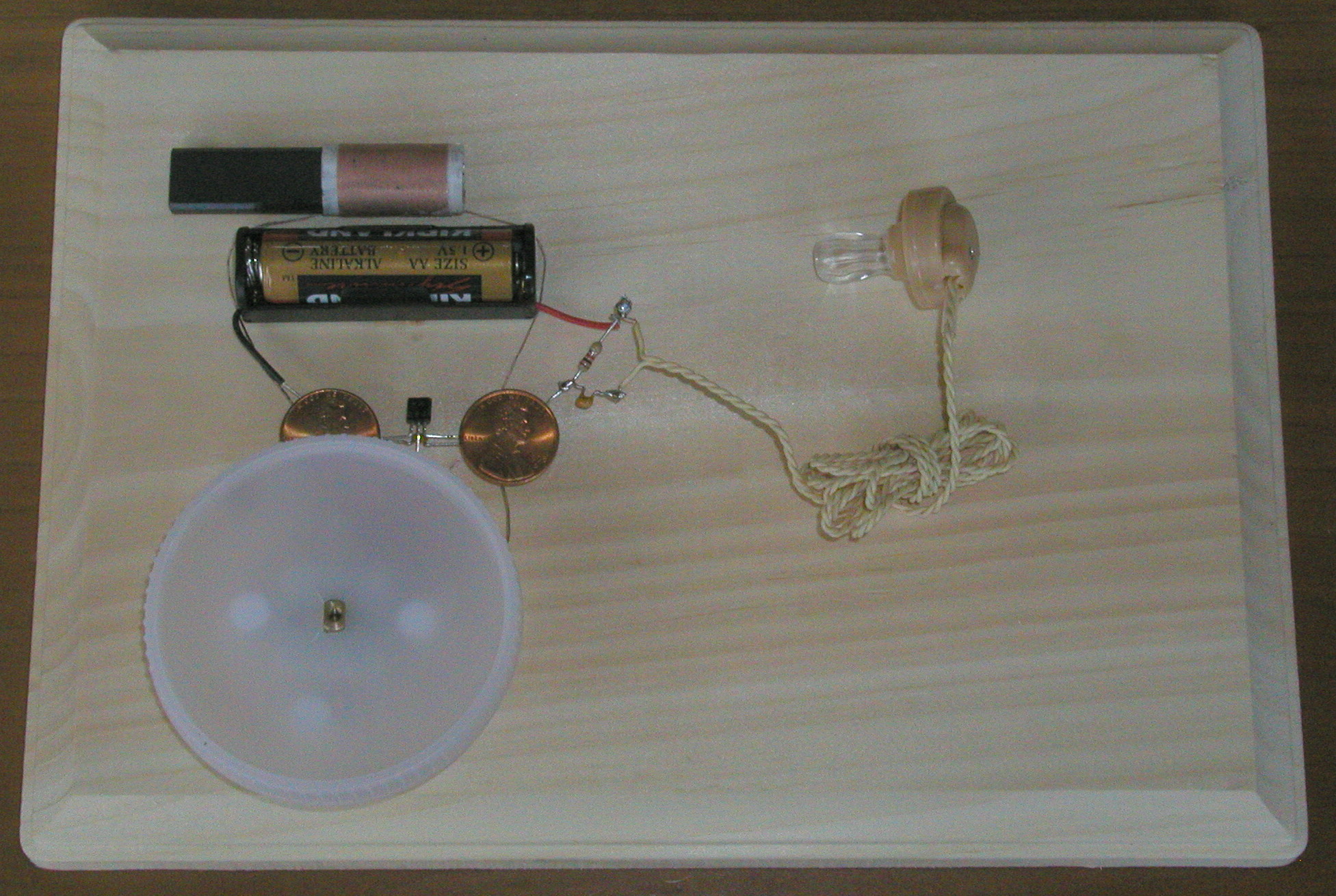
The Three Penny Radio is small enough to be fit into some fun and interesting containers. We found a nice wooden box at a local store, and built a radio to fit inside it.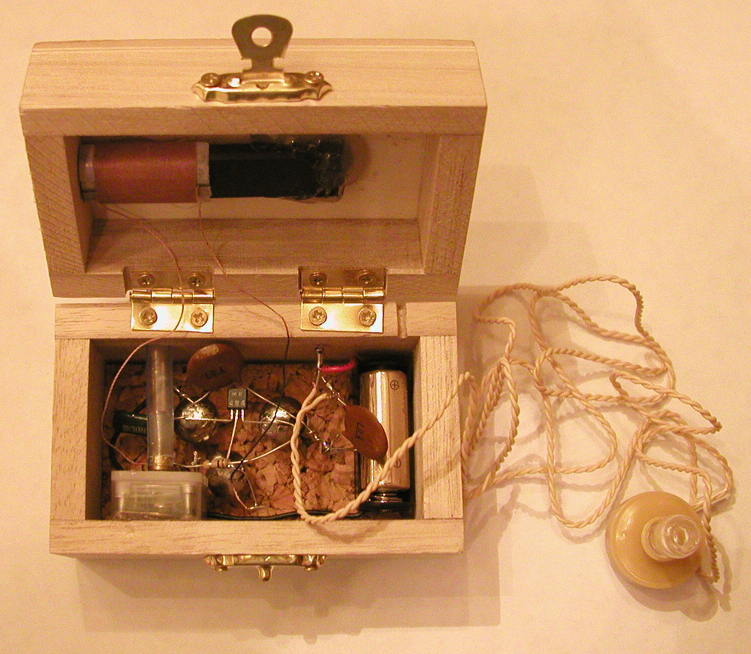
Click on photo for a larger picture
Instead of pennies, we used upholtery tacks, stuck into a bit of cork for a base. The cork was cut to fit the box.

Click on photo for a larger picture
The tuning knob is a plastic soda straw glued to the brass shaft of the variable capacitor, and exitting out of a hole drilled in the back of the box. We used a small "N" cell battery which fits nicely in the box, and powers the radio for weeks (there is no off switch). You can remove the battery when not using the radio to make it last longer. The earphone coils up inside the box for storage.
Click on photo for a larger picture
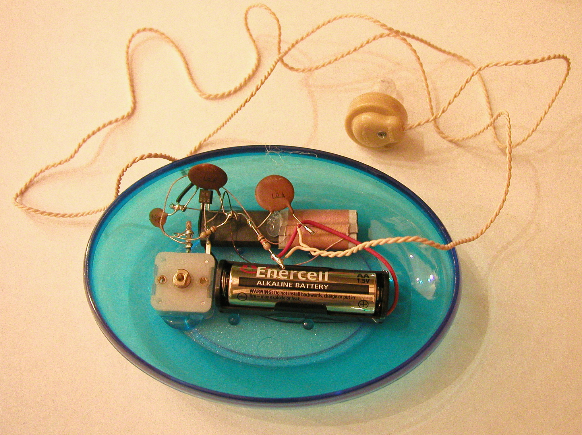
At another local store we found a little soap dish that was just begging to be turned into a radio.
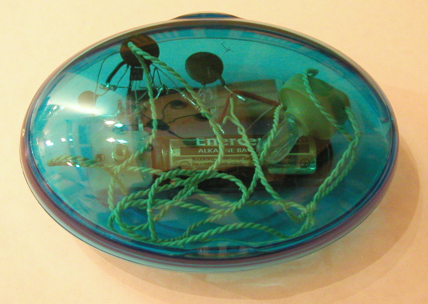
Click on photo for a larger picture
We cut a slot in the lid to let the earphone wire come out while the lid was on, so the radio fits in a shirt pocket nicely with the lid on. Like before, the earphone coils up inside the box for storage.
Tuning and Troubleshooting
Put the variable capacitor in the center of its range, and then very slowly slide the ferrite rod into the coil. As soon as you hear a little blip in the earphone, you will know you have passed up a radio station at high speed. Stop sliding the rod, and fine tune with the variable capacitor until the station comes in clearly. If you don't hear anything in the earphone, check to see if your earphone has gotten polarized by static electricity from your fingers. Touch a wire between the two bare ends of the earphone wires to connect them, while listening to the earphone. If you hear clicks and scratches, the earphone is fine. If you don't hear anything, the fix is simple. Generate some electricity in the earphone by dropping it onto a table from a height of a foot or so, then re-test. This should undo the effects of the static electricity, and get the earphone working again. Next: Thermodynamics (building heat engines) For more information on radio, see the Recommended Reading section. Del.icio.us- Science Toys
- Magnetism
- Electromagnetism
- Electrochemistry
- Radio
- Thermodynamics
- Aerodynamics
- Light and optics
- Simple laser communicator
- Make your own 3D pictures
- Making permanent rainbows.
- A solar powered marshmallow roaster
- Make a spectroscope from a CD.
- The impossible kaleidoscope
- Make a solar hotdog cooker
- Exploring invisible light
- A high resolution spectrograph.
- Time-lapse photography.
- High speed photography.
- Stacking photos for high depth of field.
- Biology
- Mathematics
- Computers and Electronics
Some of my other web sites:

Send mail to Simon Quellen Field via sfield@scitoys.com