- Science Toys
- Magnetism
- Electromagnetism
- Electrochemistry
- Radio
- Thermodynamics
- Aerodynamics
- Light and optics
- Simple laser communicator
- Make your own 3D pictures
- Making permanent rainbows.
- A solar powered marshmallow roaster
- Make a spectroscope from a CD.
- The impossible kaleidoscope
- Make a solar hotdog cooker
- Exploring invisible light
- A high resolution spectrograph.
- Time-lapse photography.
- High speed photography.
- Stacking photos for high depth of field.
- Biology
- Mathematics
- Computers and Electronics
Build a portable crystal radio

Click on photo for a larger picture
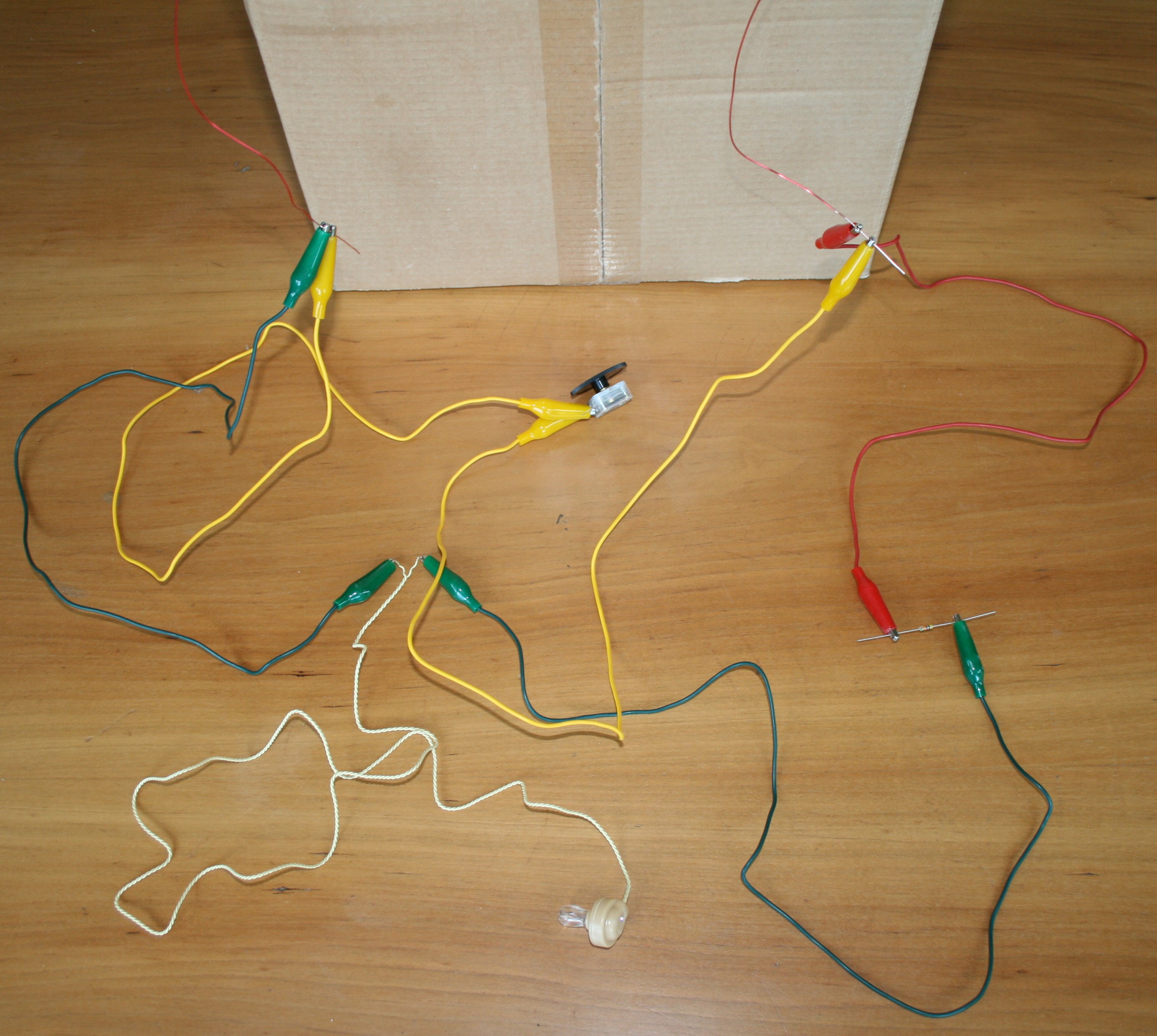
The tangled mess of colored wires pictured above is a radio. We will make it much neater in a moment, but the method of just clipping the parts together with colored alligator clips is fast and easy, and you get a working radio in a few minutes. This radio is very similar to our Ten Minute Radio project, but it takes a while to wind a coil of wire around a cardboard box to use instead of the pre-made ferrite rod tuning coil we used in that project. But what we get from winding our own coil is freedom from both a long wire antenna and the ground connection to the cold water pipe. We'll explain why we can do this in the "How does it do that?" section that follows the construction details. The Portable Crystal Radio needs these parts: (We carry most of the necessary parts in our catalog.)
- A cardboard box
-
I used a box 15.5 inches by 13 inches by 5.5 inches. The actual size of
the box is not critical -- anything from 8 inches on a side to 20 inches on a
side will do fine, because we will tune the coil using a variable capacitor.
- 60 feet of 22 Gauge Enameled Copper Wire
-
We carry this item in our
catalog.
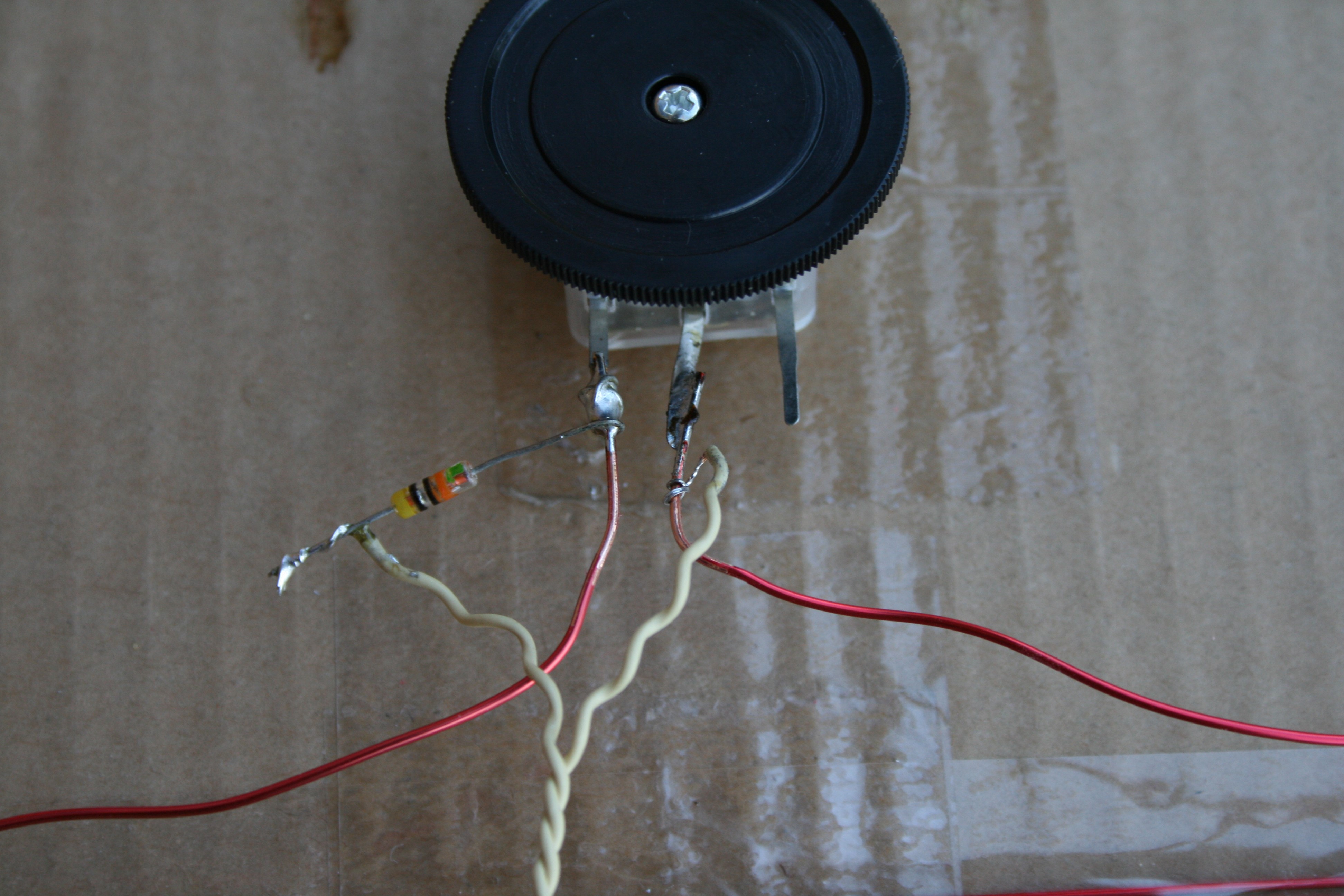
- One Variable Capacitor (0 to 160 picofarads)
-
We carry this item in our
catalog.
- One 1N34A Germanium Diode
-
We carry this item in our
catalog.
- One Piezoelectric earphone
-
We carry this item in our
catalog.
- 5 alligator test leads (optional)
-
This is a piece of wire with alligator clips at each end.
We carry this item in our
catalog.
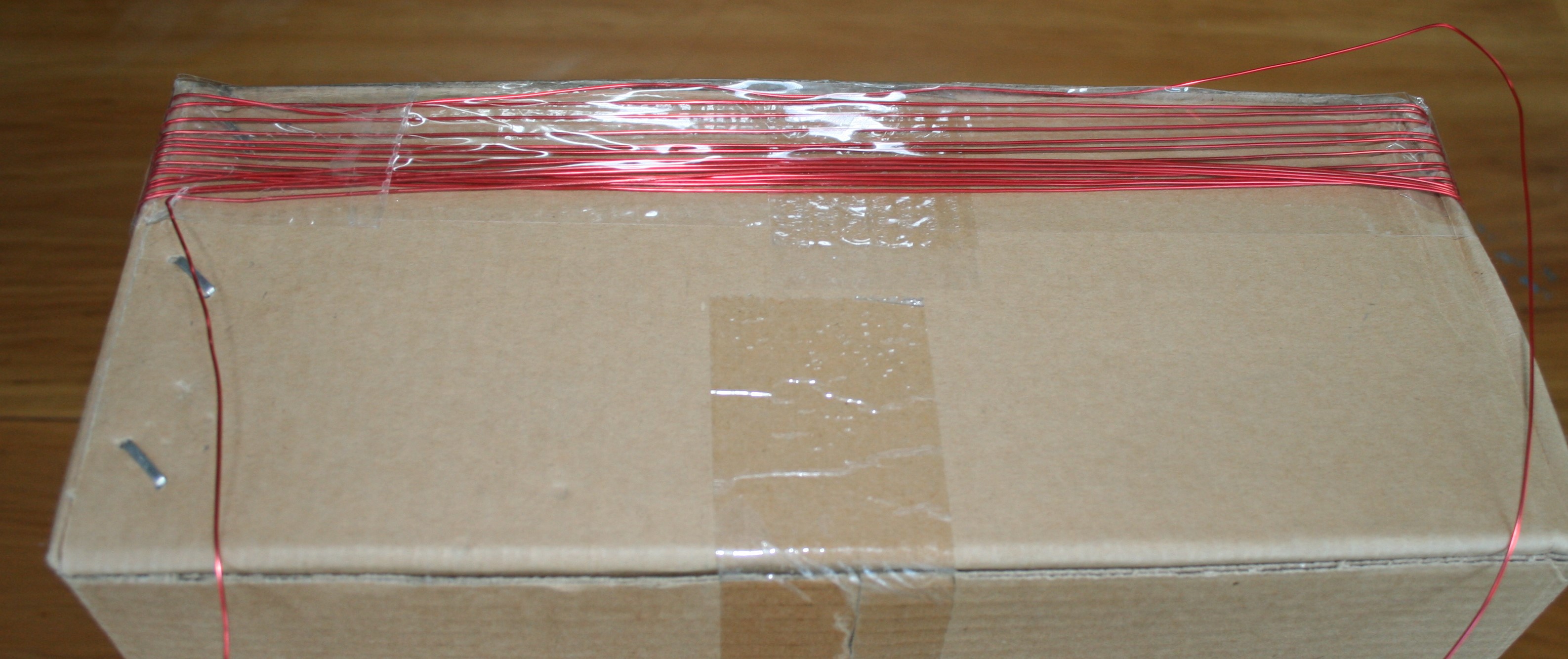
Click on photo for a larger picture
The first step is to wind the 60 feet of 22 gauge enamel coated magnet wire around the box. Depending on the size of the box you use, you will get somewhere around 8 to 25 turns of wire. The number of turns of wire, along with the variable capacitor, determines what frequency the radio receives. If you are not getting the entire AM radio band when you tune the variable capacitor, you can add or remove loops of wire from the coil, to get lower frequencies or higher frequencies. I was pretty happy with the 12 turns of wire I got from my box. You can see from the picture that I was not being particularly neat in my windings, and that having some of the wires overlap, and some of the wires separated more than others, does not appreciably affect the performance. But you will undoubtedly want a neater project than mine if you are going to show it off. You can substitute a nice picture frame or wooden box for the cardboard, or even use a block of plastic foam or some packing material. Just don't use metal. I used clear packing tape to keep the wire in place. Tape one end of the wire to the box, leaving a foot or so free to connect to the rest of the parts, and start winding. When you are almost out of wire, tape the last part down, leaving a foot free for connecting again. You can then use more tape to neatly keep all the wires in place. The last part of the coil construction is to scrape the insulation off the last inch of each of the ends of the wire, using a knife or some sandpaper.
Click on photo for a larger picture
Now we are ready to finish the radio. This part goes quickly, since we are just clipping wires to the parts. Of course it doesn't matter which color wire you use, but I will describe the colors I used, to make the descriptions simpler.

Click on photo for a larger picture
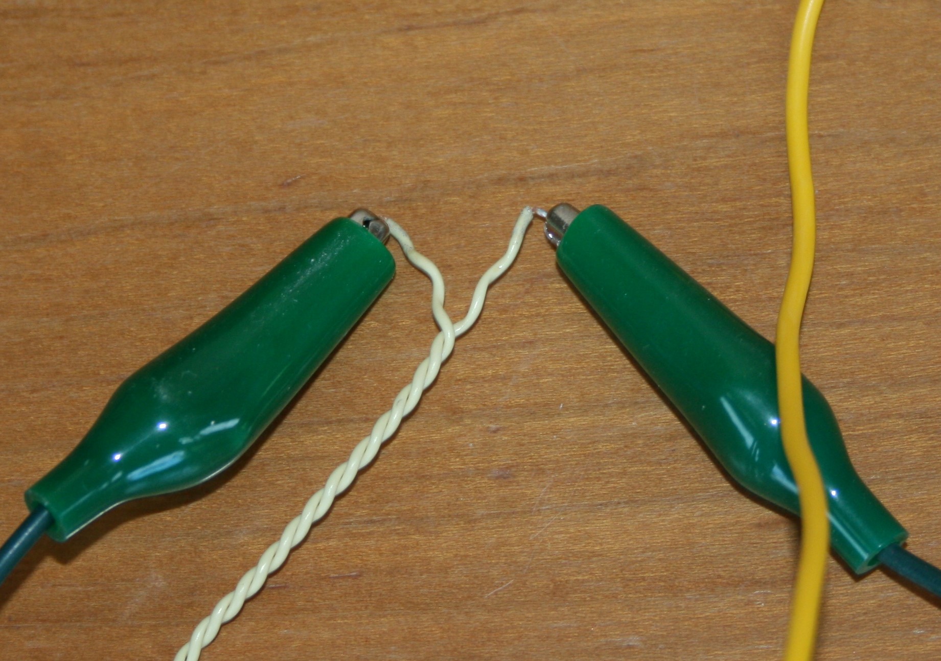
First, connect the capacitor to the coil. I used two yellow clip leads. With the dial facing away from you, the two clips go onto the center terminal and the right terminal of the capacitor. We don't use the remaining terminal. The other ends of the clip leads go onto the ends of the wires from the coil. Next, clip a green clip lead onto one wire from the coil, and a red clip lead onto the other wire from the coil.
Click on photo for a larger picture
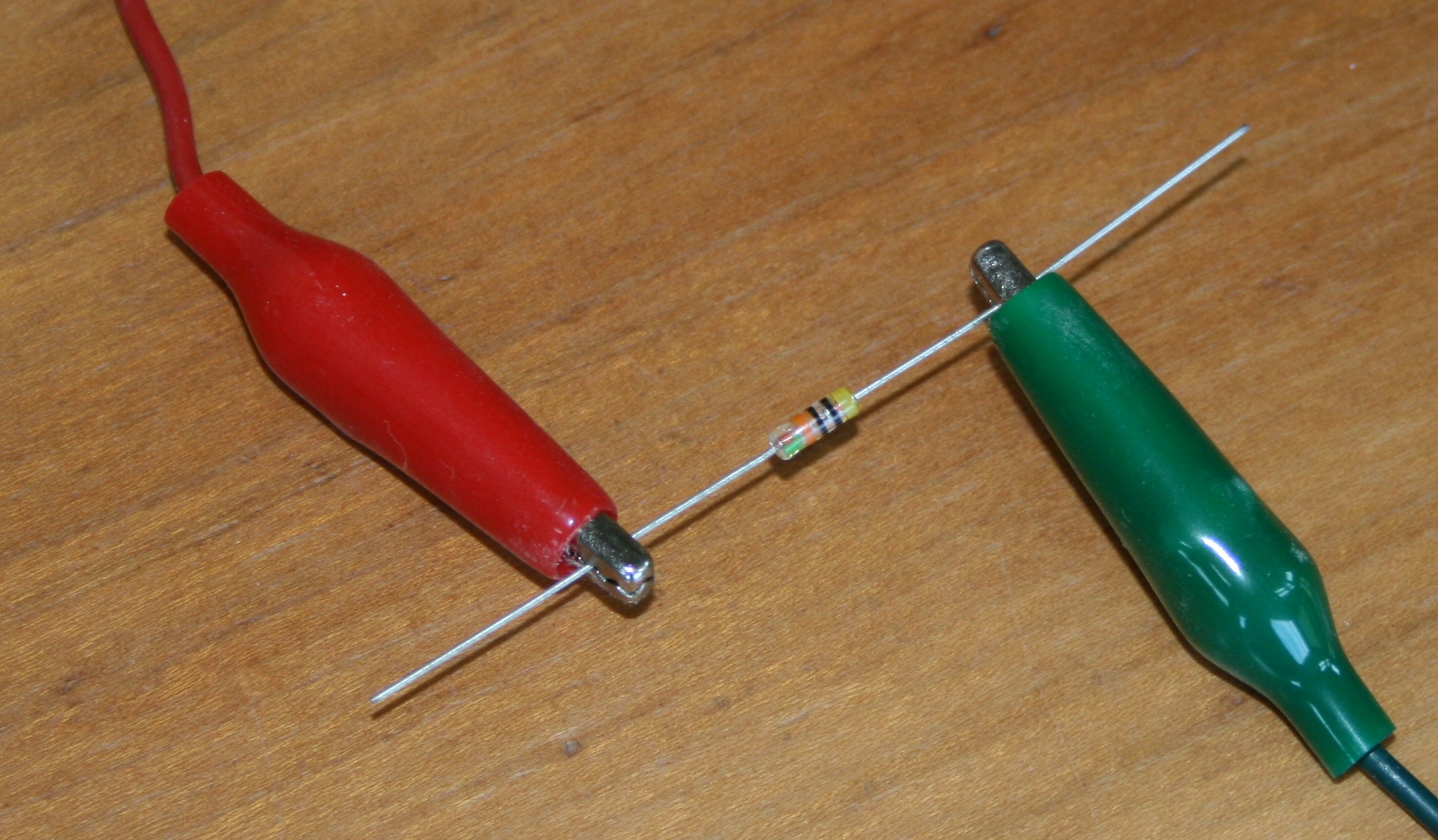
The remaining end of the red clip lead clips onto the germanium diode. It doesn't matter which end of the diode you use. Clip another alligator test lead to the other end of the diode. I used a green clip lead in the photo.
Click on photo for a larger picture
The only thing left at this point is connecting the remaining two green clip lead ends to the piezoelectric earphone. Again, it doesn't matter which wire you connect to which clip lead. Now you're finished! That's all there is to it.
Using the radio
With the earphone in your ear, tune the radio by turning the knob on the variable capacitor. Once you hear a faint radio station, move the box around to see if you can make it stronger by putting the coil broadside to the station's transmitting antenna. You can use the directionality of the coil antenna to locate where the transmitter is. Find the orientation of the coil that gives the strongest signal. The transmitting tower is either in front of the coil or behind it (since the coil picks up signals best in either direction). If one direction points to a local mountain or a nearby city, that might be a good guess at the location of the transmitter. To get a better idea of the location, try the same experiment from a few miles to the left or right, and you can triangulate. If the radio will not tune to stations with low frequencies, you can connect the two outer leads of the variable capacitor together. This will increase the capacitance, so you can reach lower frequencies. You can either solder them together, or you can use another alligator test lead. You can also wind more turns of wire on the coil to get lower frequencies, or use fewer windings to get higher frequencies.A neatly soldered version
Click on photo for a larger picture

Click on photo for a larger picture
How does it do that?
In the Ten Minute Radio, we connected the circuit to a long wire antenna, and to a pipe buried in the ground. Because the earth is so large, putting a few electrons into it or taking a few out does not change its charge. This means that we can use it as a huge reservoir of charge that never fills and never empties. The long wire lets us collect the energy in radio waves, causing the electrons in the wire to flow back and forth in time with the waves. They don't "back up" at the end of the wire because they can get to the earth, flowing in and out of that large reservoir of charge easily. But our portable radio works without either the long wire, or the connection to the ground. Actually, we do have a long wire. We just coiled it up around the box. Because the box is fairly large, we can still collect quite a bit of the energy from the radio waves, unlike the tiny coil in the Ten Minute Radio. But without the connection to the ground, where does the current go? In both radios some of the current flows in and out of the capacitor. In our portable radio, the coil is big enough to also act as an antenna, but you will get much more volume if you add a ground connection. If you have a long wire antenna, you can connect that too, and get still more volume, but you will lose one advantage (besides portability) that this radio has over the Ten Minute Radio. The coils in the loop receive radio waves better when the coil is facing the transmitter. Because the coils in the loop act as the only antenna, this directionality can help to isolate weak stations from the clutter of stonger stations. If the loop is facing the weak station, strong stations to the right or left will not be received as well, making them quieter, sometimes enough that they can't be heard at all. This directionality can be increased by making the loop larger in diameter. Doing this will reduce the number of turns in the loop. You can add more turns, getting better sensitivity, but that will also increase the inductance, so you will need a smaller capacitor in order to tune to the same frequency. The variable capacitor has a fairly wide tuining range, so you can experiment with more turns fairly easily. The directionality depends to some extent on the ratio of the diameter of the coil to the length of the coil, so adding turns can decrease the directionality if it makes the coil much longer. However, spreading out the turns reduces the capacitance of the coil, allowing you to tune to higher frequencies. It also increases the selectivity of the radio, making it easier to separate stations that are close in frequency to one another. There are thus many trade-offs you can make to optimize your radio, and lots of experimentation room to have fun getting the most out of this radio that works for free. One way to increase the selectivity of the radio is to use thicker wire in the coil, or to use copper tubing or pipe instead of wire. The lower resistance in the coil makes it tune more sharply. Next: Build simple heat engines Order radio parts and kits here.
Send mail to Simon Quellen Field via sfield@scitoys.com