- Science Toys
- Magnetism
- Electromagnetism
- Electrochemistry
- Radio
- Thermodynamics
- Aerodynamics
- Light and optics
- Simple laser communicator
- Make your own 3D pictures
- Making permanent rainbows.
- A solar powered marshmallow roaster
- Make a spectroscope from a CD.
- The impossible kaleidoscope
- Make a solar hotdog cooker
- Exploring invisible light
- A high resolution spectrograph.
- Time-lapse photography.
- High speed photography.
- Stacking photos for high depth of field.
- Biology
- Mathematics
- Computers and Electronics
A motor with two coils
In this section we will construct a motor without any permanent magnets. In place of the magnet, we will use another coil of wire. This coil is called the field coil, and the coil that moves is called the armature coil. The simplest way to do this would be to replace the permanent magnet with a coil of wire connected to a second battery. But we can save the second battery, and waste less electricity, by arranging the coils as shown in the diagram below: The diagram shows how the electrons flow in the coil.
They start where the negative terminal of the battery is
connected (marked here with a minus sign). They then flow
around and around inside the field coil until they come to
the first support loop on the right. From there they flow
into the armature coil, going round and round until they
come out the other end, and flow into the second support
loop on the left. From there they travel back to the
positive terminal of the battery.
You can see that when the electricity flows in one coil,
it also flows in the other. When the armature turns over,
and the insulation cuts off the flow of electricity to the
armature, it also cuts off the flow of electricity to the
field coil at the same time.
Because both coils turn on and off together, we never have
a condition where one coil is on when the other is off.
That would be a waste of electricity.
The diagram shows how the electrons flow in the coil.
They start where the negative terminal of the battery is
connected (marked here with a minus sign). They then flow
around and around inside the field coil until they come to
the first support loop on the right. From there they flow
into the armature coil, going round and round until they
come out the other end, and flow into the second support
loop on the left. From there they travel back to the
positive terminal of the battery.
You can see that when the electricity flows in one coil,
it also flows in the other. When the armature turns over,
and the insulation cuts off the flow of electricity to the
armature, it also cuts off the flow of electricity to the
field coil at the same time.
Because both coils turn on and off together, we never have
a condition where one coil is on when the other is off.
That would be a waste of electricity.
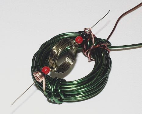 The photograph above shows the completed motor. I used three
different types of wire to more easily show how it goes together.
The heavy green wire is the field coil. It is wound with about
50 turns of wire around a D battery, then removed. The wire ends
are wrapped around the coil to keep it tight, just as we did with
the armatures of all the other motors.
One end of the field coil wire is stripped of its insulation, and
formed into a loop for the first support. The other end goes to the
battery.
A brown wire forms the second support. One end is stripped and formed
into a loop, and the other end winds around the coil a few times to
make a sturdy support, then it goes to the other terminal of the
battery.
The armature is made of thin green wire, and is formed in the same way
we did for the other motors. A couple of plastic beads keep the armature
centered (they are optional).
This motor works fine running from a D cell, and runs faster from a
9 volt battery.
Next: Fun with high voltage
Del.icio.us
The photograph above shows the completed motor. I used three
different types of wire to more easily show how it goes together.
The heavy green wire is the field coil. It is wound with about
50 turns of wire around a D battery, then removed. The wire ends
are wrapped around the coil to keep it tight, just as we did with
the armatures of all the other motors.
One end of the field coil wire is stripped of its insulation, and
formed into a loop for the first support. The other end goes to the
battery.
A brown wire forms the second support. One end is stripped and formed
into a loop, and the other end winds around the coil a few times to
make a sturdy support, then it goes to the other terminal of the
battery.
The armature is made of thin green wire, and is formed in the same way
we did for the other motors. A couple of plastic beads keep the armature
centered (they are optional).
This motor works fine running from a D cell, and runs faster from a
9 volt battery.
Next: Fun with high voltage
Del.icio.us
- Science Toys
- Magnetism
- Electromagnetism
- Electrochemistry
- Radio
- Thermodynamics
- Aerodynamics
- Light and optics
- Simple laser communicator
- Make your own 3D pictures
- Making permanent rainbows.
- A solar powered marshmallow roaster
- Make a spectroscope from a CD.
- The impossible kaleidoscope
- Make a solar hotdog cooker
- Exploring invisible light
- A high resolution spectrograph.
- Time-lapse photography.
- High speed photography.
- Stacking photos for high depth of field.
- Biology
- Mathematics
- Computers and Electronics
Some of my other web sites:

Send mail to Simon Quellen Field via sfield@scitoys.com