- Science Toys
- Magnetism
- Electromagnetism
- Electrochemistry
- Radio
- Thermodynamics
- Aerodynamics
- Light and optics
- Simple laser communicator
- Make your own 3D pictures
- Making permanent rainbows.
- A solar powered marshmallow roaster
- Make a spectroscope from a CD.
- The impossible kaleidoscope
- Make a solar hotdog cooker
- Exploring invisible light
- A high resolution spectrograph.
- Time-lapse photography.
- High speed photography.
- Stacking photos for high depth of field.
- Biology
- Mathematics
- Computers and Electronics
Building a very simple AM voice transmitter
If a crystal radio is the distilled essence of a radio, this transmitter is the matching distilled essence of transmitters. The transmitter goes together in about 10 minutes, and is small enough to fit in the palm of your hand.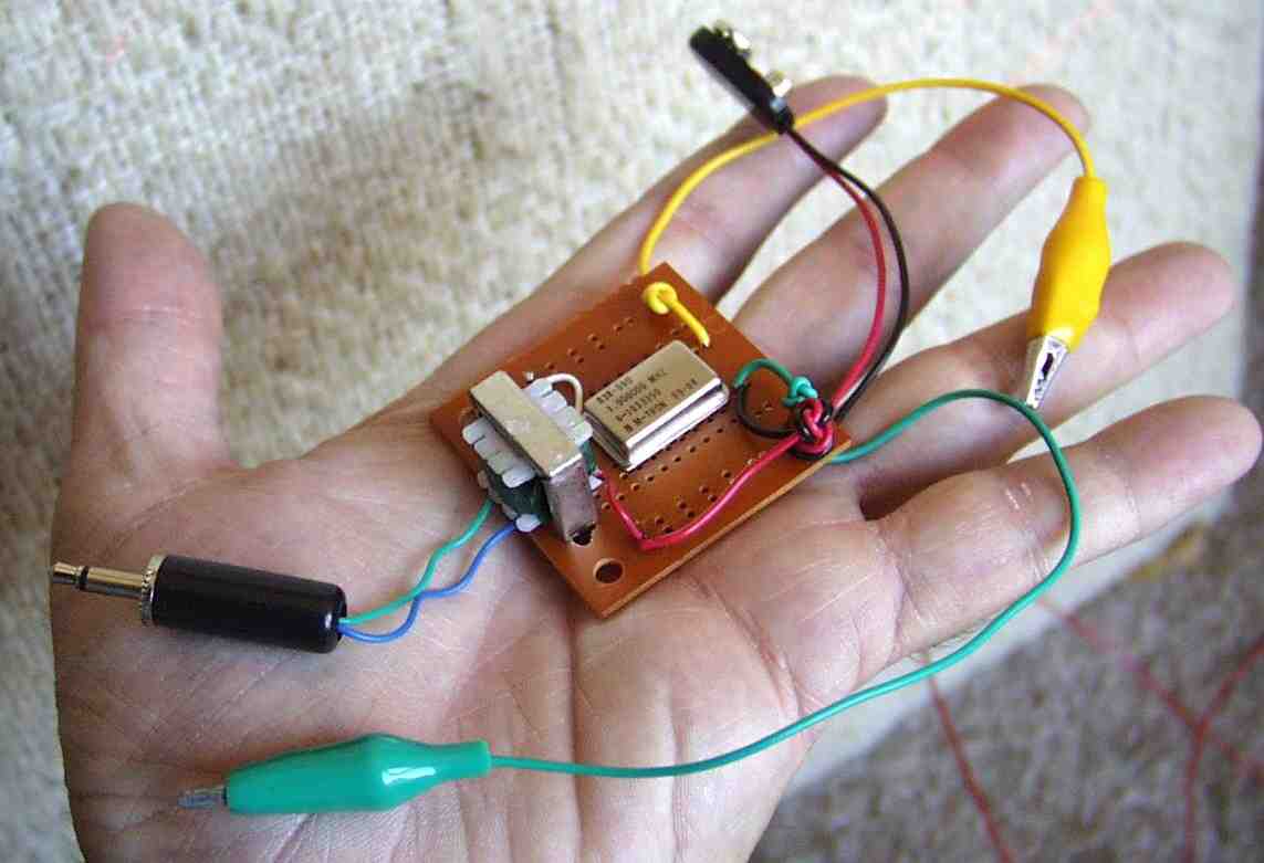
Click on photo for a larger view
Depending on the antenna, the transmitter can send voice and music across the room, or across the street. I put together my first version with simple clip leads (no soldering, no printed circuit board, not even a battery clip). This version is much sturdier and convenient.
An AM transmitter from simple parts
Our transmitter will need these parts:-
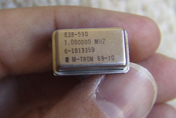
A one megahertz crystal oscillator
This is a crystal clock oscillator such as those used in computers. There are many suppliers, such as
We also carry this item in our catalog. -
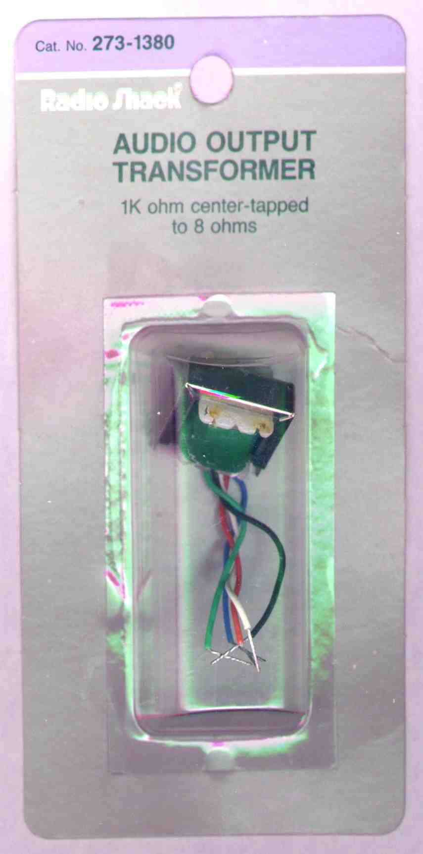
An audio transformer
This is a 1000 ohm to 8 ohm audio transformer, such as Radio Shack #273-1380.We also carry this item in our catalog.
-
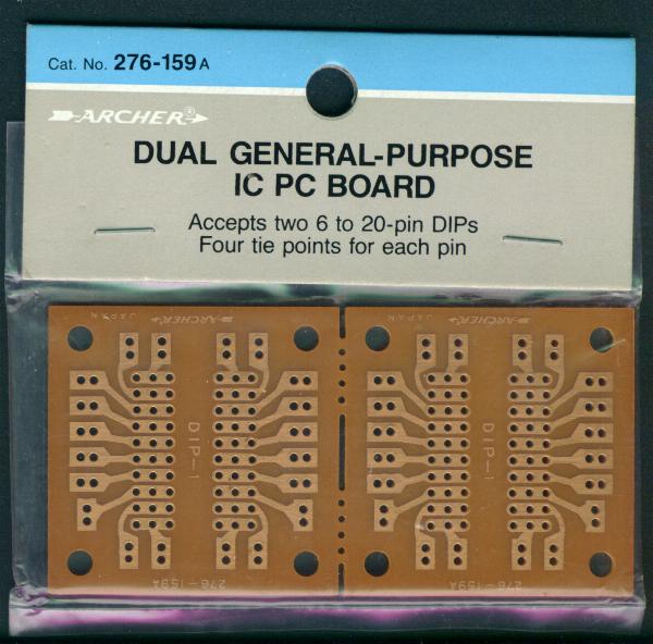
A generic printed circuit board
I used Radio Shack's #276-159A, but any general purpose printed circuit board will do.
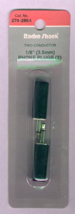
- A phone plug
This should match the jack in your sound source. I use a 1/8 inch (Radio Shack #274-286A) plug to match standard earphone jacks of transistor radios and Radio Shack's Archer mini-amplifier speaker.
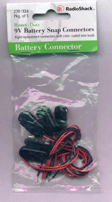
- A 9 volt battery clip
I like the Radio Shack heavy duty type, part number 270-324.
- A 9 volt battery
- A set of alligator jumpers.
Radio Shack part number 278-1156, or you can find them anywhere electronics parts are sold.
- Some insulated wire for an antenna.
You can use the same antenna you used for the crystal radio.
Building the transmitter
The oscillator is the heart of the transmitter. It has four leads, but we only use three of them. When the power is connected to two of the leads, the voltage on third lead starts jumping between 0 volts and 5 volts, one million times each second. The oscillator is built into a metal can. The corners of the can are rounded, except for the lower left corner, which is sharp. This indicates the where the unused lead is. The lead is there to help hold the can down firmly on the printed circuit board, but it is not connected to anything inside the can. The other main part is the audio transformer . In this circuit it is used as a modulator. The modulator changes the strength of the radio waves to match the loudness of the music or voice we want to transmit. A pictorial diagram of the transmitter looks like this: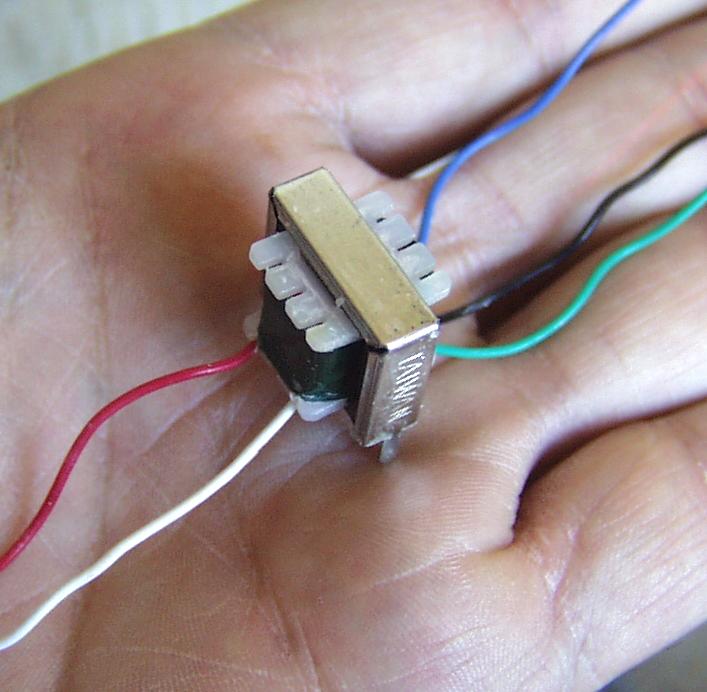
 A photograph of the completed transmitter is shown below:
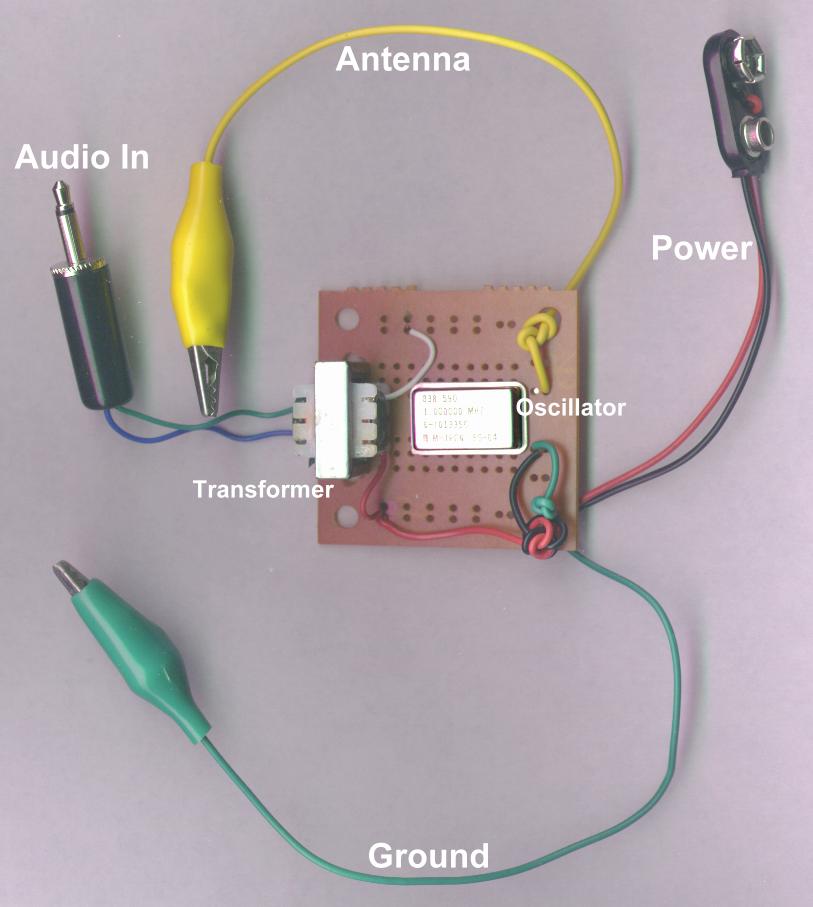
Click on photo for a larger view
The transformer has two leads on one side, (red and white in the photo ) and three leads on the other side (blue, black and green in the photo). The two leads are the low impedance side of the transformer, (the 8 ohm side). The three leads are the high impedance side (the 1000 ohm side). The middle of the three leads is called the center tap, and we won't be using it in this circuit. To get the best range, we put the low impedance side of the transformer in series with the oscillator. This means that the signal source must be capable of driving heavy loads, like an 8 ohm speaker. If you are trying to use a weaker signal source, such as an iPod or some other MP3 player that can only drive 32 ohm earphones, you will want to reverse the transformer, so that the 1,000 ohm side is in series with the oscillator, and the 8 ohm side is connected to your signal source. You will get slightle less range, but your odds of getting some modulation of the signal will be much better.
Putting it together
The transformer has two metal tabs on the bottom. These can be bent out flat, so the transformer can be glued to the printed circuit board, or two holes can be drilled in the board, and the tabs can fit into the holes and be folded over to hold the transformer in place. If you choose to drill the holes and fold over the tabs, the tabs can be soldered to the copper pads on the back of the printed circuit board for a more secure anchor. The transformer should be placed on the left side of the printed circuit board, leaving plenty of room on the right for the oscillator. Insert the leads of the oscillator into the printed circuit board, placing it far to the right. The copper side of the board should be down, with the oscillator on the side without copper. Gently bend the leads of the oscillator over, so it is held firmly onto the printed circuit board. Solder the pins of the oscillator to the copper foil of the printed circuit board. Be careful not to use too much solder, or it may form bridges of solder between copper traces that are not supposed to be connected together. Insert the stripped end of the red wire into a convenient unused hole in the printed circuit board (such as the bottom left hole). Insert the red wire from the battery clip into a nearby hole that is connected by copper foil to the first hole, so the two red wires are electrically connected. Solder the two wires to the copper foil. Insert the white transformer wire into a hole whose copper foil is connected to the upper left pin of the oscillator. Solder this wire to its copper foil. Cut one of the clip leads in half, so you have two pieces of wire each with an aligator clip attached. In the photo, I used two different colors for clarity (yellow and green). Strip the insulation from the last half inch of each piece. Insert the black wire of the battery clip into a hole whose copper foil connects to the lower right pin of the oscillator. Insert the stripped end of one of the aligator clip leads into a hole that is also connected to the lower right pin of the oscillator. Solder the two wires to the copper foil. The aligator clip will be the ground connection, just like in the crystal radio. Insert the stripped end of the other aligator clip into a hole that is connected to the top right pin of the oscillator. Solder the wire to the copper foil. This will be the antenna connector. Open the phone plug, and insert the blue and green wires of the transformer into the plastic handle. The metal part of the plug has two pieces, each with a small hole. Put one of the transformer wires into one hole and solder it, then put the other wire into the other hole and solder it. When the metal has cooled, screw the plastic handle back onto the metal phone plug.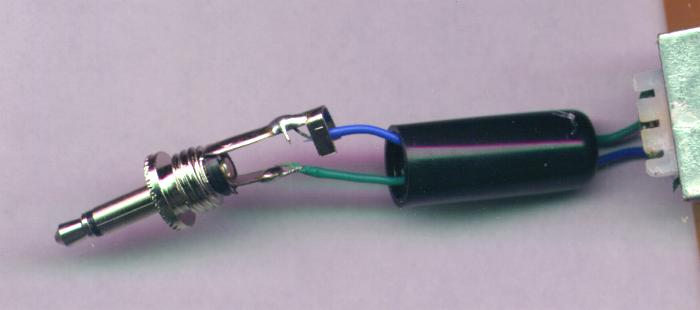
Using the transmitter
We are now ready to test the transmitter. Plug the phone plug into the earphone jack of a convenient sound source, such as a transistor radio, tape player, or CD player. Plug the batter into the batter clip. Hold the transmitter near an AM radio, and tune the radio to 1000, so you can hear the your sound source in the AM radio. Adjust the volume controls on the sound source and on the AM radio to get the best sound. Without any connection to an antenna or a good ground connection, the transmitter will only transmit to a receiver a few inches away. To get better range, clip the ground wire to a good ground, such as a cold water pipe, and the antenna to a long wire, like the one we used for the crystal radio. Many countries limit the length of the antenna you are allowed to use without a license, so check with your local laws before using a wire more than a yard or two long. For a science fair project, the transmitter and receiver can be placed within a few feet of one another, and a short wire antenna should be just fine.How does it do that?
The oscillator is connected to one end of a long wire antenna. It alternately applies 9 volts of electricity to the end of the wire, and then 0 volts, over and over again, a million times each second. The electric charge travels up and down the wire antenna, causing radio waves to be emitted from the wire. These radio waves are picked up by the AM radio, amplified, and used to make the speaker cone move back and forth, creating sound. The sound source (your CD player, or tape recorder) is normally connected to drive a speaker or earphone. It drives the speaker by emitting electricity that goes up and down in power to match the up and down pressure of the sound waves that were recorded. This moves the speaker in and out, recreating the sound waves by pushing the air in and out of your ears.
Sound waves
In our transmitter, the sound source is connected to the transformer
instead of to a speaker.
The transformer is connected to the power supply of the oscillator.
The sound source causes the transformer to add and subtract power
from the oscillator, just as it would have pushed and pulled
on the speaker.
As the power to the oscillator goes up and down, the power of the
electricity in the antenna goes up and down also. The
voltage is no longer simply 9 volts. It is now varying between
0 volts and 10 volts, because the power from the transformer
adds and subtracts from the power of the battery.
Power into antenna
The varying power in the antenna causes radio waves to be emitted.
The radio waves follow the same curves as the waves in the antenna.
However, because the transmitter and the receiver are not connected,
the receiver does not know what the transmitter is using for the
value of zero. All the receiver sees is a radio wave whose amplitude
is varying. In the receiver, zero is the average power of the wave.
This makes the wave look like this:
Radio waves in free space
If we sent this wave to the earphone, we would hear nothing,
because the average power is zero. This is why our crystal
radio has a diode.
The diode does a neat little trick.
A diode only lets electricity flow in one direction.
This means that the part of the graph where the power is rising
up from zero can get through the diode, but the part where the
power is going down from zero is blocked.
Electrical signal after the diode
All those little peaks of power happening a million times
per second are too fast for human ears, and too fast for
the earphone to reproduce. But since they are all pushing
on the earphone diaphragm, all those little pushes add up,
and the earphone moves. Since some of the little pushes
are stronger than others (taller blue bars in the illustration)
they move the earphone more than the weaker ones. We hear
this variation as sound.
Sound waves reaching our ears
The sound is a faithful reproduction of the original sound
wave at the transmitter.
For more information on radio, see the
Recommended Reading
section.
Next: Building the Three-Penny Radio
Order radio parts and kits
here.
Del.icio.us
- Science Toys
- Magnetism
- Electromagnetism
- Electrochemistry
- Radio
- Thermodynamics
- Aerodynamics
- Light and optics
- Simple laser communicator
- Make your own 3D pictures
- Making permanent rainbows.
- A solar powered marshmallow roaster
- Make a spectroscope from a CD.
- The impossible kaleidoscope
- Make a solar hotdog cooker
- Exploring invisible light
- A high resolution spectrograph.
- Time-lapse photography.
- High speed photography.
- Stacking photos for high depth of field.
- Biology
- Mathematics
- Computers and Electronics
Some of my other web sites:

Send mail to Simon Quellen Field via sfield@scitoys.com