- Science Toys
- Magnetism
- Electromagnetism
- Electrochemistry
- Radio
- Thermodynamics
- Aerodynamics
- Light and optics
- Simple laser communicator
- Make your own 3D pictures
- Making permanent rainbows.
- A solar powered marshmallow roaster
- Make a spectroscope from a CD.
- The impossible kaleidoscope
- Make a solar hotdog cooker
- Exploring invisible light
- A high resolution spectrograph.
- Time-lapse photography.
- High speed photography.
- Stacking photos for high depth of field.
- Biology
- Mathematics
- Computers and Electronics
Building a crystal radio out of household items.
A piezoelectric earphone
The most difficult part of building a crystal radio is building an efficient earphone that can convert the tiny electrical signals into tiny sounds that our ears can hear. Our first radio used a telephone handset for an earphone, and that works quite well. But another type of earphone is available that fits in the ear so you don't have to hold it. It is also more sensitive than the telephone handset. In order to convert very faint electrical signals into sound, we need a very sensitive earphone. The kind of earphones used in transistor radios or CD players will not do. Those are meant to be driven by a signal loud enough to drive a speaker, and are not sensitive at all. We will talk later (in the scientific part of this chapter) about impedance and what it means. For now, we will just say that a sensitive earphone has a very high impedance, which is measured in ohms. A speaker has a low impedance, usually about 8 ohms. A sensitive earphone built around an electromagnet (we will build one of these later) might have 2,000 ohms. The telephone handset earphone is of this type, although it has only a few hundred ohms of impedance, and will not be as loud as a more sensitive device. The crystal earphone we will play with in this section has over a million ohms of impedance, and is very sensitive. A crystal earphone (more properly called a piezoelectric earphone, pronounced pee-zo) is made of a material that changes its shape when connected to a source of electricity. Some crystals such as quartz, and Rochelle's Salt are piezoelectric. Some ceramics (such as those made with barium titanate) are also piezoelectric. Our piezoelectric earphone is made of a disk of brass that is coated with barium titanate ceramic. When electricity is connected to it, the ceramic bends the brass disk, and we can hear the vibrations this causes in the air. To make piezoelectric earphones easier for our readers to find, we now offer them in our catalog. To demonstrate just how sensitive a crystal earphone is, try this experiment: with the earphone in your ear, touch the two wires together. You will hear a sharp click as electrons move from one wire to the other. If the earphone came with a jack on the end instead of two bare wires, you will need a piece of metal such as a spoon to connect the two metal parts of the jack. One detail about such a very sensitive earphone is important in building a crystal radio. A sensitive earphone does not use very much current to create the sound. Another way of saying this, is that not much current is going through the earphone. Our radio needs a certain amount of current to flow through the diode in order to work. When substituting a piezoelectric earphone for an earphone made with a coil of wire, we must provide a way for some current to bypass the earphone. We do this by putting a resistor or a coil in parallel with the earphone (parallel means that the resistor or coil is attached to the same two places that the earphone wires are attached). The resistor can be anything in the range of 1,000 ohms to 100,000 ohms, and can be a piece of graphite out of a pencil, or a couple hundred coils of fine wire around a nail.A Germanium diode detector
The second part of our radio, after the earphone, is the detector. A detector is something that picks the audio frequencies out of a radio wave, so they can be heard in the earphone. We will learn more about how they work in the scientific part of the chapter later on. Our first detector will be store-bought. Later we will replace it with detectors we build ourselves out of things we find around the house, like lead pencils, baking soda, razor blades, rocks, all kinds of things. The detector we will use first is a Germanium diode. The diode we want is called a 1N34A by the people who name diodes. This diode has some properties that make it particularly suited to our purpose, namely that it works at lower voltage levels than most other common diodes. Since the voltage in our radio comes from weak little radio waves, we need all the help we can get. We now carry this diode in our catalog, to make it easier to obtain. Radio Shack used to carry them, but they no longer have them in their stores.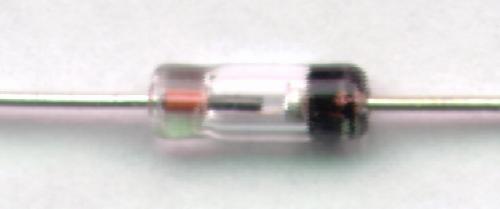 We are now ready to build our simplest radio.
A very simple radio with two parts
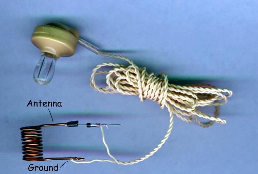
First let me warn you that this first little radio may not work in your location. It relies on having a very strong local radio station to overcome the limitations of such a simple radio. If it does not work where you are, you can either build its cousins that we will discuss later, or you can drive out closer to a local radio station, and try it there. But because it is so simple, you might try building it just to see what you might be able to pick up. If your earphone has a jack on the end, cut it off, so you have two long wires coming from the earphone. If the wires are twisted around each other, that is OK, since we only need them to be separate at the very ends. Remove the covering (called insulation) from the ends of the wires to expose an inch of bare wire. Often you can do this with your fingernail, but a tool called a wire stripper is made for this purpose, and can usually be purchased at the same place you got the earphone or the diode. Wrap one bare wire around one of the diode's wires. Use some tape to keep it in place. If you know how to solder, you can solder the wires together, but it really isn't necessary for now.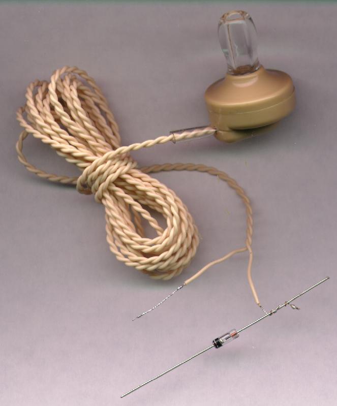 Tape the other diode wire to a cold water faucet. This makes a good
connection to the ground, and is thus called a 'ground' connection.
Hold the remaining free bare wire of the earphone in your hand. This
makes your body into the antenna for the radio. Put the earphone in
your ear. If you are close to a strong AM radio station, you will be
able to hear that station faintly in the earphone. You may hear more
than one station at once.
If you can't hear anything, you might try a better antenna. You can
tape the wire you were holding to a metal window screen, or a long
wire. If one end of the long wire is thrown up on a roof or in a
tree, you might get better results. Another good antenna is an
outdoor TV antenna. Just touch the free earphone wire to one of
the antenna terminals where it comes into the TV. If you have a good
antenna, you may be able to eliminate the ground connection, using
your body as a ground instead, by holding the free diode wire in
your hand.
Tape the other diode wire to a cold water faucet. This makes a good
connection to the ground, and is thus called a 'ground' connection.
Hold the remaining free bare wire of the earphone in your hand. This
makes your body into the antenna for the radio. Put the earphone in
your ear. If you are close to a strong AM radio station, you will be
able to hear that station faintly in the earphone. You may hear more
than one station at once.
If you can't hear anything, you might try a better antenna. You can
tape the wire you were holding to a metal window screen, or a long
wire. If one end of the long wire is thrown up on a roof or in a
tree, you might get better results. Another good antenna is an
outdoor TV antenna. Just touch the free earphone wire to one of
the antenna terminals where it comes into the TV. If you have a good
antenna, you may be able to eliminate the ground connection, using
your body as a ground instead, by holding the free diode wire in
your hand.
Another simple radio with two parts
Our simple radio has two main drawbacks. One is that the signals are very faint, and can only be heard if you are close to a radio station's transmitting antenna. The other is that you hear all of the strong stations at once, and it is hard to pick out just one song or voice from the mixed up jumble. The first problem is called the 'sensitivity' of the radio. Our radio is not very sensitive. The second problem is called the 'selectivity' of the radio. Our radio is not very selective. We can solve both problems by using a trick called resonance. Resonance is a way of taking a little bit of energy, and using it over and over again, at just the right time, to accomplish a big task. We use resonance when we push someone on a swing. It would take a lot of work to lift someone several feet in the air, but we can do this easily on a swing by giving a little push over and over again at just the right time. Timing is important: if we push at the wrong time, the swing can actually lose energy instead of getting higher. When an opera singer uses her voice to shatter a wine glass, she is using resonance. Her voice gives the glass a little push at just the right time, over and over again, until the glass is moving so far that it shatters. In a similar way, we can slosh all the water out of a bathtub by moving a hand in the water at just the right back and forth speed. Each time the hand moves, the water climbs a little higher, until it is over the top of the tub. Radio waves can act like the sound waves of the singer's voice, or like the waves in the bathtub. Radio waves can cause electrons to move back and forth in a wire, just like the water in the tub. If the radio waves are moving back and forth at the right frequency, then the electrons in the wire will just be crowding towards one end of the wire when the radio waves start moving them back to the other side. Just like the water in the tub, the electrons will crowd higher and higher at the ends of the wire. These electrons can do work, like moving the brass disk in the earphone to create sound. We can use resonance to build a radio that can pick up only one station at a time, and make a louder sound in the earphone. This radio will also have some drawbacks (for one thing it will be over 1,000 feet long!) but we will solve these problems in the next radio we build. Suppose we pick a local radio station we want to hear. For this example we will choose 740 kilohertz on the AM dial. We now need to figure out how long the wire must be to resonate at this frequency. Radio waves travel at the speed of light. This radio wave is going back and forth 740,000 times per second. This means the wave needs to go about a quarter of a mile in one direction, then turn around and go back again, over and over. The actual formula for figuring out how long the wire should be is
936 feet
Frequency in Megahertz
or, for our example:
Frequency in Megahertz
936 feet
.740
or about 1264 feet.
To make our radio, we take half of the wire (632 feet) and attach it
to one end of the diode. We attach the other half of the wire to
the other end of the diode. We attach one earphone wire to one side of the
diode also, and the other earphone wire to the other end. We put the
long wire up in the air by attaching each end to a tree (the trees
must be about 1264 feet apart). Then we put the earphone into our
ear, and listen to the radio.
Now I can think of a couple problems with this radio. It is not the
most portable radio. Also, in order to change the station, we need
to make the wire longer or shorter.
One solution to the portability problem is to coil the wire up by
winding it on a box or a cylinder. Then we can solve the tuning
problem by attaching the diode and earphone to the coil at different
places (easy to do now that the whole wire is in one small place).
.740
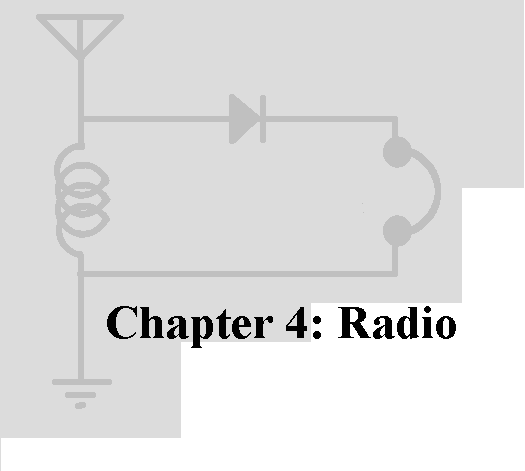
A simple radio with three parts
There are several ways to connect a coil of wire to a diode and earphone to make a radio. In the photos below, we show two possibilities that work.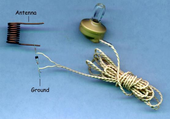 The photos do not show the antenna and ground connections,
but instead indicate where they would be attached.
The photos do not show the antenna and ground connections,
but instead indicate where they would be attached.
 The coil in the photos is also dramatically simplified. A real
coil for the AM radio frequencies would be somewhat larger, as we
saw when we built our first radio using the plastic bottle.
Often photographs show so much detail that the important parts
are easily missed. By using a simplified drawing, we can accentuate
the important parts of the circuit and leave out unimportant or
distracting details that can interfere with getting the point across.
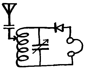
A simplified drawing of a circuit is called a schematic.
A schematic for a simple crystal radio might look like this if drawn
on a napkin at a party:
The coil in the photos is also dramatically simplified. A real
coil for the AM radio frequencies would be somewhat larger, as we
saw when we built our first radio using the plastic bottle.
Often photographs show so much detail that the important parts
are easily missed. By using a simplified drawing, we can accentuate
the important parts of the circuit and leave out unimportant or
distracting details that can interfere with getting the point across.
A simplified drawing of a circuit is called a schematic.
A schematic for a simple crystal radio might look like this if drawn
on a napkin at a party:
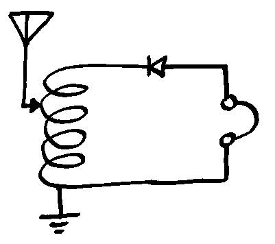 The symbol for a coil looks like a spring. The symbol for an antenna
looks like someone used a coat hanger. The symbol for headphones looks
like the old fashioned ear-muff style (which are great for crystal
radios, since they block out ambient noise in the room). The symbol
for the ground looks like what a cartoonist would draw under a cartoon
character to represent the earth.
Note that the antenna is attached to the coil in the middle by a small
arrow. This indicates that it is attached to a tap in the coil. An arrow
is used to indicate a connection that can move, like our clip lead.
The symbol for the diode looks nothing like the little glass tube with
wires coming out. Instead of represeting what the diode looks like,
it represents what the diode does.
A diode is a one-way valve for electricity. The electric current flows
through the diode in one direction, but is blocked if it tries to flow
in the other direction. We will find out why this is important later,
when we learn why the radio works. But for now, we will concentrate on
building a radio that will let us hear one station at a time, with
reasonable loudness.
The symbol for a coil looks like a spring. The symbol for an antenna
looks like someone used a coat hanger. The symbol for headphones looks
like the old fashioned ear-muff style (which are great for crystal
radios, since they block out ambient noise in the room). The symbol
for the ground looks like what a cartoonist would draw under a cartoon
character to represent the earth.
Note that the antenna is attached to the coil in the middle by a small
arrow. This indicates that it is attached to a tap in the coil. An arrow
is used to indicate a connection that can move, like our clip lead.
The symbol for the diode looks nothing like the little glass tube with
wires coming out. Instead of represeting what the diode looks like,
it represents what the diode does.
A diode is a one-way valve for electricity. The electric current flows
through the diode in one direction, but is blocked if it tries to flow
in the other direction. We will find out why this is important later,
when we learn why the radio works. But for now, we will concentrate on
building a radio that will let us hear one station at a time, with
reasonable loudness.
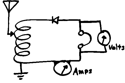
Power from radio waves -- hooking up a meter to measure the voltage and current
It is useful at this point to be able to measure the effects of changes we make to the radio. We can just use our ears and try to remember how loud it used to be, but it is easier to read a meter, and remember a number. With a meter connected to the radio we can adjust the tuning for the highest meter reading, or make other adjustments as we add new components or replace purchased components with ones we make ourselves. The meters must be sensitive to very small changes in the amount of electricity flowing in our radio. We will be measuring current mostly, but we will add a voltmeter as well, so we can calculate the total amount of energy we are receiving. Current is the flow of electricity through the circuit, and it is measured in amperes, or amps for short. Voltage is the pressure that pushes the current through the wires. If electicity were water, current would be the amount of water flowing (gallons per minute), and voltage would be the water pressure in pounds per square inch. Since the amount of current is very small, we will use a meter that measures current in micro-amperes, or at most small fractions of a milliampere. Some examples of microammeters and milliammeters can be seen in the photo below: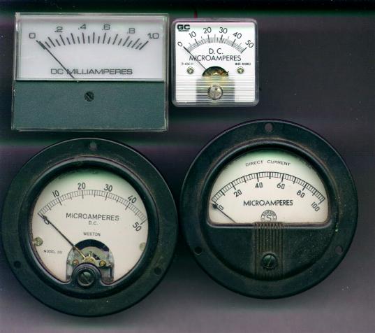 To measure the current in our radio, we will need to have the current
flowing through the meter. To do this, we connect the microammeter
between the earphone and the ground connection, so that any electricity
that is going to flow throught the earphones to make noise is going to
have to flow through the meter also. The meter can be connected in two
ways, one is forward and one is backward. If the meter is connected
backward, the needle will start reading below zero. If this happens,
just reverse the connections, so the needle reads above zero.
To measure the voltage, we connect the meter to both of the earphone
wires. The schematic diagram now looks like this:
To measure the current in our radio, we will need to have the current
flowing through the meter. To do this, we connect the microammeter
between the earphone and the ground connection, so that any electricity
that is going to flow throught the earphones to make noise is going to
have to flow through the meter also. The meter can be connected in two
ways, one is forward and one is backward. If the meter is connected
backward, the needle will start reading below zero. If this happens,
just reverse the connections, so the needle reads above zero.
To measure the voltage, we connect the meter to both of the earphone
wires. The schematic diagram now looks like this:
 If you have a good antenna, or a strong radio station nearby, the ammeter
might read more than 50 microamps. If you have a short antenna, you might
get only 5 microamps and still be able to hear the station clearly in the
headphones. I put up a 200 foot antenna between two trees over my house,
and tuned to a 50,000 watt station about 30 miles away, and now I get
175 microamps of current through my meter. I put the earphone to the mouth
of a cone (like a megaphone) and I can clearly hear the radio from across
the room when the house is quiet. It doesn't sound as nice and clear as it
does with the earphone right up to my ear, but I can follow a conversation
easily (it's an all-news station).
The voltmeter in the same radio reads 125 millivolts. Since watts (the
measure of how much power we have) is the voltage multiplied by the
amperes, we have 0.000175 times 0.125, or 0.0000218 watts, or about 22
microwatts. The station is putting out 50 killowatts, and we are receiving
one ten billionth of that power, yet we can hear it across the room.
Try different lengths of antenna, and watch the current go up as the longer
antennas catch more of the power from the radio station. Try more that one
antenna. Try connecting the ground wire to different things that are connected
to the ground, such as pipes, metal fences, etc. As you try each test, make
sure you tune the radio again, because your changes may affect the tuning.
If you have a good antenna, or a strong radio station nearby, the ammeter
might read more than 50 microamps. If you have a short antenna, you might
get only 5 microamps and still be able to hear the station clearly in the
headphones. I put up a 200 foot antenna between two trees over my house,
and tuned to a 50,000 watt station about 30 miles away, and now I get
175 microamps of current through my meter. I put the earphone to the mouth
of a cone (like a megaphone) and I can clearly hear the radio from across
the room when the house is quiet. It doesn't sound as nice and clear as it
does with the earphone right up to my ear, but I can follow a conversation
easily (it's an all-news station).
The voltmeter in the same radio reads 125 millivolts. Since watts (the
measure of how much power we have) is the voltage multiplied by the
amperes, we have 0.000175 times 0.125, or 0.0000218 watts, or about 22
microwatts. The station is putting out 50 killowatts, and we are receiving
one ten billionth of that power, yet we can hear it across the room.
Try different lengths of antenna, and watch the current go up as the longer
antennas catch more of the power from the radio station. Try more that one
antenna. Try connecting the ground wire to different things that are connected
to the ground, such as pipes, metal fences, etc. As you try each test, make
sure you tune the radio again, because your changes may affect the tuning.
Adding a capacitor (or three)
As you tried different antenna lengths, you may have noticed that you had to move the tap on the coil in order to get the station at its loudest. To understand why this happens, and how we can use an understanding of it to improve our radio, we must first understand capacitance and how it affects the tuning coil. A capacitor is simply two pieces of metal with an insulator between them. If a capacitor is connected to a battery, the battery will push electrons onto one piece of metal (called a plate) and draw electrons from the other piece of metal. If we remove the battery, the electrons can't go anywhere, so one plate of the capacitor will have more electrons than the other plate. If we connect the two plates together with a wire, the electrons will rush from the plate that had too many (because electrons have the same charge, and thus repel each other like the north poles of two magnets) to the plate that had fewer electrons. As the electrons rush from one plate to the other, we can make them do work, such as light a light bulb. In this way, the capacitor seems to store the electricity from the battery, for use at another time when the battery isn't there. Now suppose we connect a coil and a capacitor together like this: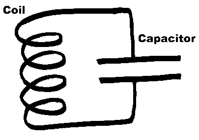 Suppose also that the capacitor has been charged by a battery so the top
plate has more electrons than the bottom plate. When we connect the coil,
the excess electrons in the top plate immediately start traveling through
the coil to get to the plate that has a shortage of electrons.
As the electrons travel through the coil, they create a magnetic field,
(remember 'coil' is just another word for 'electromagnet'). The magnetic
field grows until the plates on the capacitor have equalized. At this
point you would think the current would stop flowing in the coil. But
the magnetic field that built up when the current flowed through the coil
now starts to collapse.
Just as moving a magnet past a coil will generate
a current, a collapsing magnetic field around a coil creates a current too.
The current is in the same direction as it was when the magnetic field was
created, so the coil ends up pushing electrons onto the bottom plate of
the capacitor, and stealing them from the top plate.
By the time the magnetic field around the coil has completely collapsed,
the bottom plate of the capacitor has a surplus of electrons, and the top
plate has a deficit. You can guess what happens next.
The electrons start flowing back into the coil, this time from the bottom
plate to the top. The coil starts building up a magnetic field again, but
since the current is now going the other way, what used to be the north
pole of the magnetic field is now the south pole, and vice-versa.
The field grows until the capacitor has equalized, then it collapses, and
pumps electrons into the top plate of the capacitor. We are now back where
we started, and the whole process starts over again!
The coil and the capacitor are resonating, just like the child on a swing,
or the water in a bathtub. In fact, this circuit is called a 'tank circuit',
like a tank full of water that sloshes back and forth.
We can control the frequency of the oscillations in two ways. We can make the
coil larger or smaller, or we can make the capacitor larger or smaller.
The coil we built for our radio has taps, which have the effect of making the
coil shorter or longer, depending on which tap we connect to the antenna.
Our radio has a coil. But it doesn't have a capacitor. Or does it?
Actually, the antenna itself is acting like a capacitor. The capacitance
of the antenna is reacting with the inductance of the coil to
resonate at the frequency of the radio station.
When we change the length of the antenna, it is like changing the size of
the capacitor. This is why changing the length of the antenna changed the
tuning of the radio, forcing us to move to a different tap on the coil in
order to listen to the same station.
There is another way to change the capacitance of a capacitor. We can change
the distance between the two plates. If the plates are closer together, the
excess electrons on one plate are attracted to the other plate, because when
the negatively charged electrons were removed from that plate,
it was left with a positive charge.
Because the electrons are attracted to the positive charge, we can pile more
of them together, storing more energy. In a similar fashion, when we make
a capacitor with the plates farther apart, the positive charge is farther away,
and can't help to pull as many electrons onto the negative plate. Thus the
amount of energy we can store is less, and we say the capacitor has less
capacity
We can combine capacitors to raise or lower the capacitance, now that we know
how capacitors work. If we put two capacitors together in parallel, we can
increase the capacitance, because the top plates are connected together, and
the bottom plates are connected together, it is just as if we had one
capacitor with large plates.
Suppose also that the capacitor has been charged by a battery so the top
plate has more electrons than the bottom plate. When we connect the coil,
the excess electrons in the top plate immediately start traveling through
the coil to get to the plate that has a shortage of electrons.
As the electrons travel through the coil, they create a magnetic field,
(remember 'coil' is just another word for 'electromagnet'). The magnetic
field grows until the plates on the capacitor have equalized. At this
point you would think the current would stop flowing in the coil. But
the magnetic field that built up when the current flowed through the coil
now starts to collapse.
Just as moving a magnet past a coil will generate
a current, a collapsing magnetic field around a coil creates a current too.
The current is in the same direction as it was when the magnetic field was
created, so the coil ends up pushing electrons onto the bottom plate of
the capacitor, and stealing them from the top plate.
By the time the magnetic field around the coil has completely collapsed,
the bottom plate of the capacitor has a surplus of electrons, and the top
plate has a deficit. You can guess what happens next.
The electrons start flowing back into the coil, this time from the bottom
plate to the top. The coil starts building up a magnetic field again, but
since the current is now going the other way, what used to be the north
pole of the magnetic field is now the south pole, and vice-versa.
The field grows until the capacitor has equalized, then it collapses, and
pumps electrons into the top plate of the capacitor. We are now back where
we started, and the whole process starts over again!
The coil and the capacitor are resonating, just like the child on a swing,
or the water in a bathtub. In fact, this circuit is called a 'tank circuit',
like a tank full of water that sloshes back and forth.
We can control the frequency of the oscillations in two ways. We can make the
coil larger or smaller, or we can make the capacitor larger or smaller.
The coil we built for our radio has taps, which have the effect of making the
coil shorter or longer, depending on which tap we connect to the antenna.
Our radio has a coil. But it doesn't have a capacitor. Or does it?
Actually, the antenna itself is acting like a capacitor. The capacitance
of the antenna is reacting with the inductance of the coil to
resonate at the frequency of the radio station.
When we change the length of the antenna, it is like changing the size of
the capacitor. This is why changing the length of the antenna changed the
tuning of the radio, forcing us to move to a different tap on the coil in
order to listen to the same station.
There is another way to change the capacitance of a capacitor. We can change
the distance between the two plates. If the plates are closer together, the
excess electrons on one plate are attracted to the other plate, because when
the negatively charged electrons were removed from that plate,
it was left with a positive charge.
Because the electrons are attracted to the positive charge, we can pile more
of them together, storing more energy. In a similar fashion, when we make
a capacitor with the plates farther apart, the positive charge is farther away,
and can't help to pull as many electrons onto the negative plate. Thus the
amount of energy we can store is less, and we say the capacitor has less
capacity
We can combine capacitors to raise or lower the capacitance, now that we know
how capacitors work. If we put two capacitors together in parallel, we can
increase the capacitance, because the top plates are connected together, and
the bottom plates are connected together, it is just as if we had one
capacitor with large plates.
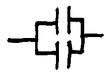 If we connect the capacitors in series, it has the effect of making the plates
of the capacitor be farther apart. This can be seen in the illustration below.
The bottom plate of one capacitor is connected to the top plate of the other.
Electrically, this is the same as making the two plates into one plate in the
middle of a capacitor that has twice the distance between the outer plates.
The phantom inner plate has no effect, and is drawn as a dotted line in the
bottom illustration.
If we connect the capacitors in series, it has the effect of making the plates
of the capacitor be farther apart. This can be seen in the illustration below.
The bottom plate of one capacitor is connected to the top plate of the other.
Electrically, this is the same as making the two plates into one plate in the
middle of a capacitor that has twice the distance between the outer plates.
The phantom inner plate has no effect, and is drawn as a dotted line in the
bottom illustration.
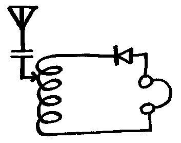
 We now know enough about capacitors to use them in our radio. We can use
a small capacitor between the antenna and the coil to lower the capacitance
of the antenna. This will allow the coil to tune to stations that are
higher in frequency. The capacitor is in series with the capacitance of the
antenna, so the total capacitance is lower.
The circuit now looks like this:
We now know enough about capacitors to use them in our radio. We can use
a small capacitor between the antenna and the coil to lower the capacitance
of the antenna. This will allow the coil to tune to stations that are
higher in frequency. The capacitor is in series with the capacitance of the
antenna, so the total capacitance is lower.
The circuit now looks like this:
Building your own capacitors
Capacitors are easy to build in the kitchen out of aluminum foil. In fact, our first capacitor will simply be two sheets of foil tucked into a paperback book, with one page separating them, as if they were two bookmarks.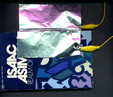 This quick capacitor has advantages and disadvantages. It is quick
and easy to build, it can be easily adjusted to vary the capacitance
by simply sliding one of the foil strips out of the book a little at
a time, thus reducing the capacitance. On the other hand, it is bulky,
and comes apart easily, and will change its capacitance when you press
down on the book, squeezing the pages closer together. Lastly, it can
change capacitance slightly on humid days as the pages of the book absorb
moisture.
With only a little more effort, we can make a durable, stable, capacitor
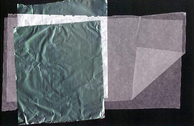
using foil and a little waxed paper or plastic wrap.
We start by laying down a sheet of waxed paper. On top of that
we lay a sheet of foil. We leave the foil hanging over the top
of the waxed paper, so we will have something to which we can attach
a wire. We lay another piece of waxed paper over the first piece
and the foil. We then lay another piece of foil on the top, overlapping
it at the bottom for our other wire. We make sure that the foil sheets
are always separated by the waxed paper, so they do not make an electrical
connection.
This quick capacitor has advantages and disadvantages. It is quick
and easy to build, it can be easily adjusted to vary the capacitance
by simply sliding one of the foil strips out of the book a little at
a time, thus reducing the capacitance. On the other hand, it is bulky,
and comes apart easily, and will change its capacitance when you press
down on the book, squeezing the pages closer together. Lastly, it can
change capacitance slightly on humid days as the pages of the book absorb
moisture.
With only a little more effort, we can make a durable, stable, capacitor
using foil and a little waxed paper or plastic wrap.
We start by laying down a sheet of waxed paper. On top of that
we lay a sheet of foil. We leave the foil hanging over the top
of the waxed paper, so we will have something to which we can attach
a wire. We lay another piece of waxed paper over the first piece
and the foil. We then lay another piece of foil on the top, overlapping
it at the bottom for our other wire. We make sure that the foil sheets
are always separated by the waxed paper, so they do not make an electrical
connection.
 Now we roll the whole thing up like a jelly roll.
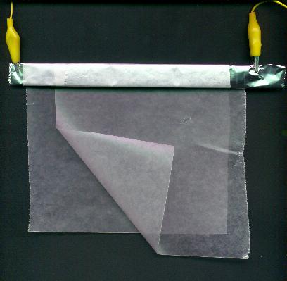 Now we trim up the paper with some scissors, and we can even roll it
up the other way to make it smaller.
Now we trim up the paper with some scissors, and we can even roll it
up the other way to make it smaller.
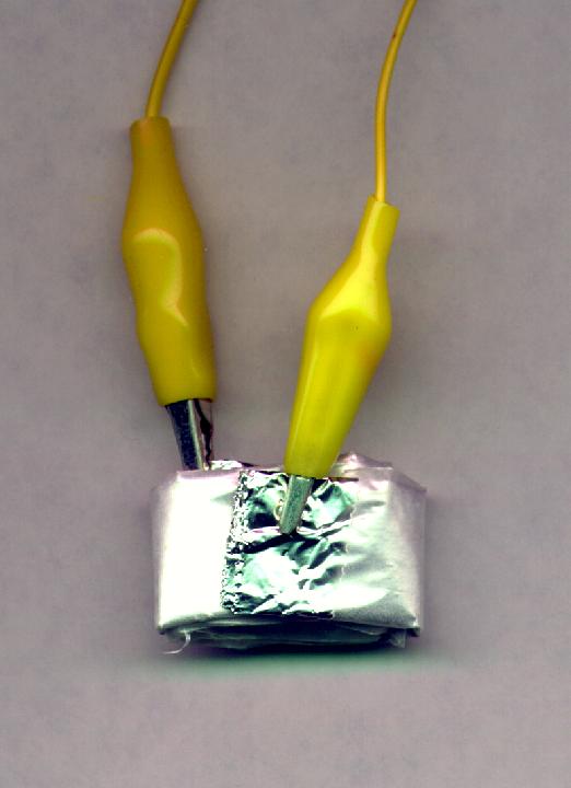 This capacitor is not adjustable like our first one, but we can make
several of them, each a different size, and connect the one we want.
We can even combine them in parallel or in series to change their
capacitance.
We can use the small fixed capacitor to tune the antenna, and
another variable capacitor (like our book capacitor) to tune the
coil. We put the variable capacitor in parallel with the coil, to make
a tank circuit. The small fixed capacitor lowers the antenna's capacitance,
making the circuit tune to a higher frequency. But the variable capacitor
adds more capacitance to the circuit, making it tune to a lower frequency.
Now we can tune the radio with the taps on the coil, and by sliding
the foil in and out of the book.
The circuit now looks like this:
This capacitor is not adjustable like our first one, but we can make
several of them, each a different size, and connect the one we want.
We can even combine them in parallel or in series to change their
capacitance.
We can use the small fixed capacitor to tune the antenna, and
another variable capacitor (like our book capacitor) to tune the
coil. We put the variable capacitor in parallel with the coil, to make
a tank circuit. The small fixed capacitor lowers the antenna's capacitance,
making the circuit tune to a higher frequency. But the variable capacitor
adds more capacitance to the circuit, making it tune to a lower frequency.
Now we can tune the radio with the taps on the coil, and by sliding
the foil in and out of the book.
The circuit now looks like this:
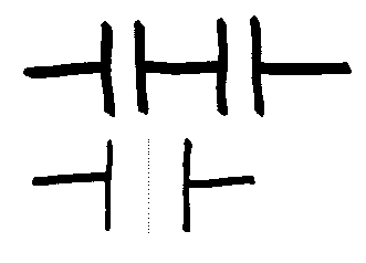
 Notice how the variable capacitor has an arrow through it to indicate that
it can change its capacitance.
Notice how the variable capacitor has an arrow through it to indicate that
it can change its capacitance.
Building your own diodes
During World War I, soldiers in the field made their own radios to listen to programs for entertainment and news. They had access to wire from broken down vehicles, and telephone receivers, but they did not have modern solid state diodes in little glass tubes. However, it is surprising to find out just how many ordinary objects can act as a diode, letting current flow one way better than another. The soldiers found that an old rusty razor blade and a pencil lead worked just fine. By lightly touching the pencil lead to spots of blue on the blade, or to spots of rust, they formed what is called a point contact diode. We can replace our store-bought diode with a homemade point contact diode and compare the results. The parts can be attached to the circuit with clip leads, or they can be soldered, as in the photo below. The pencil lead is attached to a safety pin by wrapping it with bare copper wire and soldering it.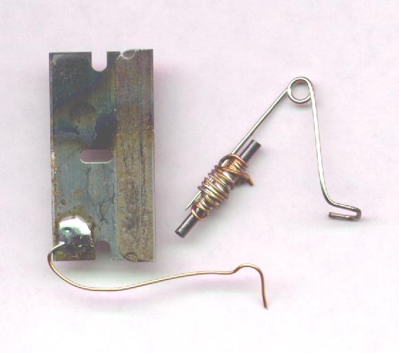 The safety pin acts as a spring to lightly press the pencil lead onto the
razor. If the pressure is too hard or not hard enough, the diode will
not work, so experiment. The exact spot on the razor is also critical,
since some spots will have too much or too little oxide on them to make
the diode. Move the pencil lead around on the razor until the sound is
loudest, or the meter (if you have attached one) reads highest.
The safety pin acts as a spring to lightly press the pencil lead onto the
razor. If the pressure is too hard or not hard enough, the diode will
not work, so experiment. The exact spot on the razor is also critical,
since some spots will have too much or too little oxide on them to make
the diode. Move the pencil lead around on the razor until the sound is
loudest, or the meter (if you have attached one) reads highest.
 In the photo above, you can see how handy the brass drawer pulls are when
we want to attach new types of diodes.
If you don't have a rusty razor blade lying around, you can try other bits
of rusty metal. The blade shown above was clean and new, so I put a little
salt and water on it, and held it in the flame of a gas stove until parts of
it were blue and purple.
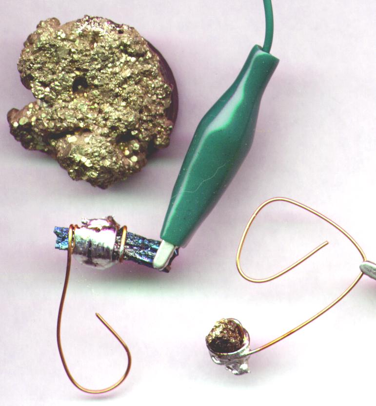
You might have other things around the house that can act as diodes. In
my rock collection, I found some iron pyrite (fool's gold) and some
carborundum (silicon carbide, the blue stone in the photo below).
The carborundum works
well with a strong pressure, so I simply wrapped some bare copper wire
around it, soldered the wire, and then let the jaws of a clip lead supply
the pressure. It works quite well. The pyrite needs a gentle touch, so
I used the point of a safety pin to gently probe until I found a spot on
the pyrite that gave good volume in the radio.
In the photo above, you can see how handy the brass drawer pulls are when
we want to attach new types of diodes.
If you don't have a rusty razor blade lying around, you can try other bits
of rusty metal. The blade shown above was clean and new, so I put a little
salt and water on it, and held it in the flame of a gas stove until parts of
it were blue and purple.
You might have other things around the house that can act as diodes. In
my rock collection, I found some iron pyrite (fool's gold) and some
carborundum (silicon carbide, the blue stone in the photo below).
The carborundum works
well with a strong pressure, so I simply wrapped some bare copper wire
around it, soldered the wire, and then let the jaws of a clip lead supply
the pressure. It works quite well. The pyrite needs a gentle touch, so
I used the point of a safety pin to gently probe until I found a spot on
the pyrite that gave good volume in the radio.
Going further - some quick thoughts
Trading loudness for more stations
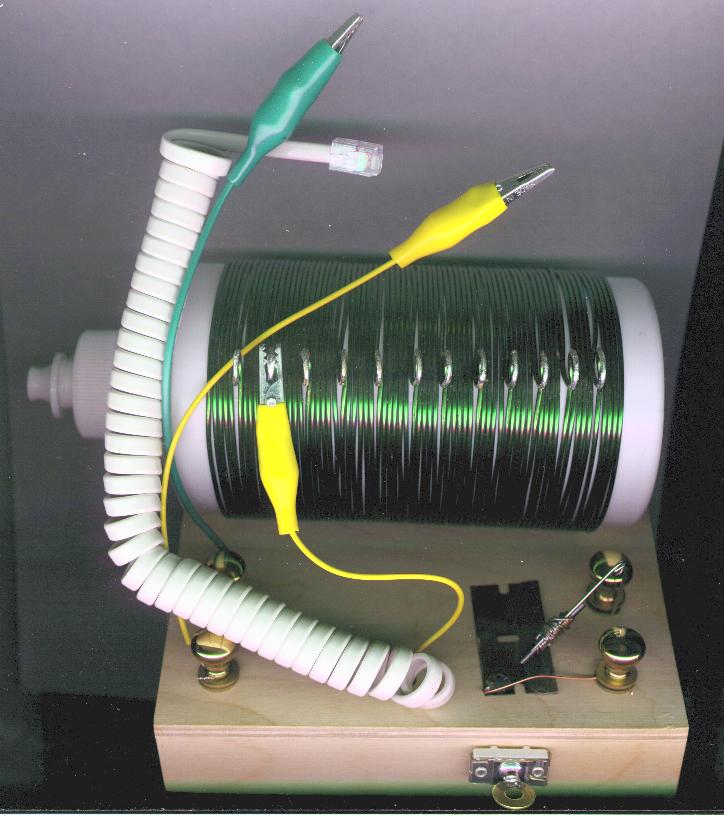
In our radio, the diode and earphones are connected directly to the antenna and ground. This connection gets the loudest signal. However, it also loads the tuning coil, making it less selective. This means that many lower power or distant stations are drowned out by local strong stations. We can make the radio more selective by decoupling the tuning coil from the antenna and ground. We do this by adding a small coil. The new coil is attached to the antenna and the ground, and then it is placed inside the main tuning coil. Wind about five or ten turns of wire around a small coil form such as the plastic container use to package 35 mm film (about 1 inch in diameter). Cut a large hole in the bottom of the plastic bottle on which we wound the large tuning coil. Attach the antenna and ground to the small coil, and place it into the large tuning coil using the new hole you just made. By moving the small coil in or out of the large coil, you can vary the coupling between the coils, and thus vary the selectivity and sensitivity of the radio. If you want loud strong local stations, place it all the way in. If you want to hear the fainter distant stations, pull it out a bit.Help with construction math
Here is a simple little program that can show you how many turns of wire you need on your tuning coil to resonate with any capacitor you choose: A coil construction calculatorBuilding your own earphones
You can build your own earphones using a tin can, a nail, a small magnet, and some fine wire. Wind a few hundred turns of wire around the nail. Let the magnet stick to the head of the nail (a neodymium-iron-boron supermagnet in our catalog works well here, since it is strong and very small). Attach the coil to the radio in place of the earphones. Hold the open end of the tin can to your ear, and hold the nail very close to the bottom of the tin can. The bottom of the can will be attracted to the magnet, but the coil will make it vibrate with the sound from the radio. A coil from an old relay or solenoid will often also work, and save you the effort of winding the wire on the nail.A seashell loudspeaker
I got a large conch shell from an aquarium store for a few dollars. Using a concrete drill, I made a 1/4 inch hole in the shell at the small end (where the shell was formed when the conch was very small). I then glued a piezo-electric earphone to the hole. This makes a nice trumpet-like megaphone and makes the sound of the radio clearly audible across a quiet room. It also looks very nice.Using an LED for a diode.
Because I have a long (150 foot) antenna, a good ground, and a strong station (50,000 watts) less than 20 miles away, my radio receives enough power to light a low current LED. The LED is a 'high brighness' type (which also means that it will light dimly with a very small amount of current). I connect it instead of diode in the radio, and it glows as the radio operates, getting brighter as the sound gets louder. If you don't have a strong station nearby, you can add a battery in series with the LED (a small 1.5 volt battery works fine). The LED will light up, and the radio will play much louder than without the battery (if the LED doesn't light up, try connecting the battery the other way around). This arrangement is the best detector I have used so far, and is louder than the 1N34A germanium diode. Next: A simple radio transmitter Order radio parts and kits here. Del.icio.us- Science Toys
- Magnetism
- Electromagnetism
- Electrochemistry
- Radio
- Thermodynamics
- Aerodynamics
- Light and optics
- Simple laser communicator
- Make your own 3D pictures
- Making permanent rainbows.
- A solar powered marshmallow roaster
- Make a spectroscope from a CD.
- The impossible kaleidoscope
- Make a solar hotdog cooker
- Exploring invisible light
- A high resolution spectrograph.
- Time-lapse photography.
- High speed photography.
- Stacking photos for high depth of field.
- Biology
- Mathematics
- Computers and Electronics
Some of my other web sites:

Send mail to Simon Quellen Field via sfield@scitoys.com